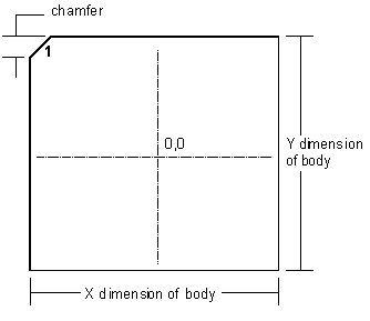
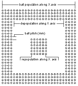

| The initial steps in creating a BGA involve laying out the array of ball pads, numbering them according to the JEDEC rules, and laying out the package outline. Artwork Conversion has developed a powerful yet simple-to-use AutoLISP routine that automates the layout. In only a minute you have the basic BGA outline. |
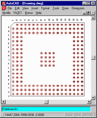
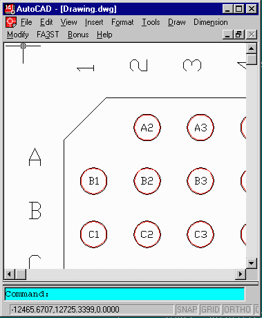
Runs Inside of AutoCAD Because so much BGA design is done on AutoCAD we implemented ARRAYGEN as an AutoLisp routine. The user opens an AutoCAD drawing, starts up the ARRAYGEN Lisp routine, enters the required parameters and watches as ARRAYGEN places the balls, the soldermask, the package outline, and assigns the JEDEC numbering. |
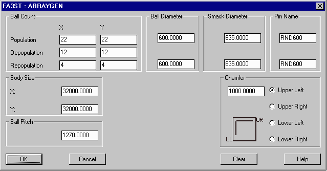
| ARRAYGEN is menu driven. Enter the package size, number of balls, ball spacing, ball diameter and solder mask diameter. From this data the outline is automatically drawn, the balls are placed and numbered. | We've recently introduced an enhancement that enables you to specify a different diameter/padstack for the repopulated ground balls. Many BGA manufacturers use a different sized ball for the ground vias under the die. |

|

|
|
Jedec Numbering In addition to placing the balls, ARRAYGEN also places the correct JEDEC numbering along the outer edge of the package and labels each ball with a block attribute. This saves the draftsman the time to set up the numbering manually. Depending on your documentation needs you can use either the outer numbering or the individual ball numbering. Solder Mask Arraygen also creates a solder mask layer; the user specifies the diameter of the solder mask and can have either a clearance from the ball or captured ball. |
|
LayeringARRAYGEN puts the different elements on individual AutoCAD layers making it easier for the designer to separate functions:
AutoCAD Layer Function BOTM Balls placed on Bottom Metal Layer BOTSM Solder mask circles placed on Bottom Solder Mask OUTLINE Package Outline BALL_NUMS JEDEC Ball numbers placed on this layer |