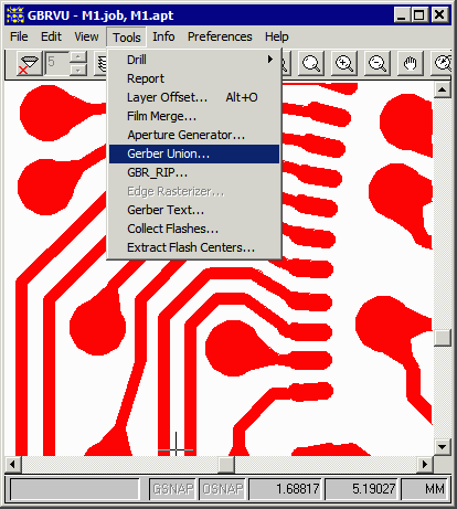
To use GBRUnion, open your Gerber file in GBRVU, turn on the layer you wish to process and then use the Tools pulldown.
Click on Gerber Union ... and the dialog will pop open.

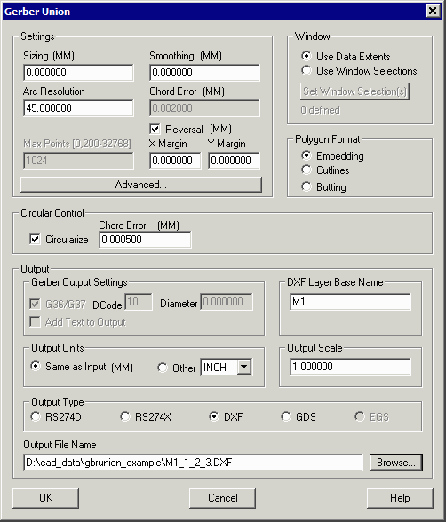
GBRUnion is configured and executed from the Gerber Union Dialog box (shown below). The various fields and options are summarized below.

Settings
If not set = zero, sizes each edge out (positive) or in (negative). This is generally used for etch compensation.
If non-zero, the smoothing value is used to remove closely spaced vertices in the output file. This can be used to reduce vertex count. (Not available if Circular Boolean is selected)
if arcs are not preserved (currently this applies to aperture macros) this value tells GBRUnion how to fracture an arc by specifying the angle that each chord will subtend. Values range from about 2 degrees to 45 degrees. The lower the value the more vertices are generated and the smoother the approximation.
if arcs are not preserved this value tells GBRUnion how to fracture an arc by specifying the maximum error between the center of the chord and the ideal arc. This parameter is more flexible than Arc Resolution since it takes into account the arc's radius. If planning to use Chord error, it is recommended to set Arc Resolution = 45 degrees.
Max Points
When polygon output is set to cut lines or butting, then the user can limit the maximum number of points in a polygon.
If reversal is checked, then the output will be constructed to generate a polarity reversal. The margin is added to the actual extents of the elements being reversed.
Advanced...
Click here to see the contents of the Advanced Settings dialog.
Window
The user can select the window to be either based on the data's extents box, or the user can select their own window using GBRVU.
Circular Control
If Circularize is selected (requires a special license to enable this function) the second generation Boolean is used which preserves arcs. This normally results in much smaller and smoother output files. Cannot be used for GDSII output.
Polygon Format
Embedding - polarity changes are implemented by creating a new layer for each level of polarity. This is commonly used for Gerber and DXF output but never for GDSII output.
Cutlines - islands are formed using a cut-line which is a path into and out of the polygon respecting the winding rule.
Butting - islands are formed by "slicing" a polygon with a hole resulting in two (or more) polygons that do not have holes.
Sliver
A Sliver is a small artifact often resulting from a Boolean operation between polygons. Or it may be a small artifact in the input layout data that you wish to remove. Very often it is generated when subtracting a shape that was originally an arc. Slivers end up isolated from the desired polygon.
Output
The Output section controls the type of output and various settings for each of the outputs; it also controls the file destination.
Gerber Output Setting
If RS274X has been selected as the Output Type, this section controls options:
G36/G37 - when checked, polygons are written using the G36/G37 area fill command; if unchecked, then the user should specify a D-code to use for the polygon and the D-code's diameter.
Add text to output - when checked (what exactly does this do?)
DXF Layer Base Name
Since embedding can create multiple paint and scratch layers, the user specifies the desired base name and each DXF layer is appended with _1, _2, _3 ...
Output Units
If Same as Input is selected, the output file units match the input file units. If other is checked, then select an output unit from the drop down.
Output Scale
The default is 1. If set to some other value the output data is scaled up or down as specified.
Output Type
The radio buttons allow the user to specify one of the available output types: RS274D (older Gerber format), RS274X (modern Gerber format), DXF (AutoCAD's data exchange format), GDSII (IC mask layout database) and EGS (Agilent ADS). If an option is grayed out then it is not licensed for use.
Output File Name
Enables the user to set the path and output file name.