You can start WireBond from:
- The main bond dialog box (press the Wirebond button)
- AutoCAD (start AutoCAD and use the Wirebond pulldown)
- typing: wb.exe from a DOS Box
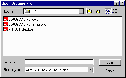
You will be prompted to open the package drawing file:

|
This module is used to wirebond your die into the package of your choice. Prior to running Wirebond you should already have completed the following steps:
At this point you have all of the necessary data files in hand and you are ready to use Wirebond to attach the bond wires from die to package, check the resulting wires against your design rules, update the title border to reflect the various part numbers and plot your results.
|
|
Starting WireBond You can start WireBond from:
You will be prompted to open the package drawing file:
|
|
The program will load this file and automatically launch AutoCAD with the
WireBond button box open.
The button box is designed to take you step-by-step through the wirebonding process. Here is a quick summary of what each step does:
|
| Number Fingers | Program prompts you to identify bond finger #1 and to specify CW or CCW Rotation. Program proceeds to number and label the fingers. |
| Insert Die | Select the die drawing, scale, rotate or mirror, place it. |
| Wirebond | Select and edit (optional) the connection list. Wirebond will attach wires. Optionally, select 1:1 and wirebond will attach each die pad to the appropriate finger. |
| Die Image | Select the AutoCAD drawing containing the image of the die. Wirebond will place it (properly rotated and mirrored and scaled) so that it is about 90 percent the size of the die. This gives the operator a good idea of what the die should look like. |
| BDD Text | Opens a dialog box and reads existing annotations from the title border. User adds/modifies items such as the device number, mask number etc.... Program automatically enters these into the appropriate part of the title border. |
| AMD Logo | User specifies on the package where die pad 1 should appear. Program inserts an asterix (*) there and a note in the drawing indicating that this is where the "AMD logo" will appear. |
| Save | Saves your work. |
| Plot | Aids the designer in creating the correct plot: size, orientation, destination plotter or PDF file. |
| Clear | If you mess up and want to clear only work done by Wirebond, press this button. Enables you to go back to the beginning and start again. |
| Exit | Exits the button box menu. This needs to be done occasionally if you wish to pan and zoom through your AutoCAD drawing or to do other commands that require focus be changed to the main AutoCAD window. You can freely exit the button box menu without losing any work. You can return to the button box menu. (Just don't quit your session of AutoCAD). |