Device Cleaner

The device cleaner module does the following:
  • Extracts pad ring from a large GDSII file
  • Flattens the data
  • Converts it to AutoCAD's DXF file format
  • Opens AutoCAD and loads the pad ring data
  • Identifies pads based on size/geometry
  • Finds center of die pad
  • Enables user to add/delete die pads
  • Asks user to identify pad 1
  • Autocenters the device around 0,0
  • Saves as an AutoCAD dwg


  • The Main Menu

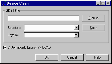
    The user selects the GDSII file to process. Device Clean will scan the file and present the user with the list of structures and layers that contain data. The user should then enter the top level structure and should also enter the layer that contains the pad ring.

    dc1.gif


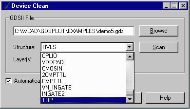
    The user is selecting the "TOP" structure from the GDSII file called demo5.gds.

    dc4.gif


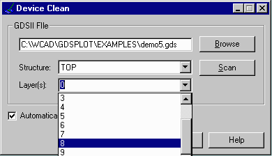
    The user selects layer 8 as the layer that contains the pad ring.

    dc5.gif


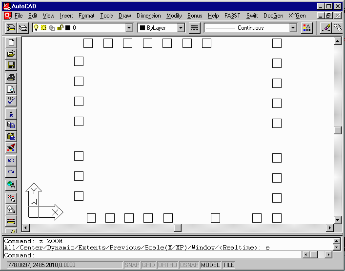
    Upon hitting OK, the device clean routine will extract all data on layer 8. It will then explode the hierarchy and convert the data to AutoCAD's DXF file format. If the Automatically Launch AutoCAD button is checked, the program will then start AutoCAD and pass it the DXF file.

    dc6.gif


    Identifying the Die Pads

    Once AutoCAD has started the pad identification routine begins immediately. Pads are identified based on several criteria:

    • their size relative to the extents of the die

    • the number of sides

    • their aspect ratio

    This algorithm has proven to be very robust. However in the case that a die pad is missed or an entity that is not a die pad is accepted, the user has a dialog box that enables him to add or delete die pads.

    A total count of die pads is displayed - most users will know how many die pads should exist and this verifies that all the pads have been identified.

    dc7.gif


    Numbering and Classifying the Die Pads

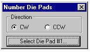
    The next step is to number and classify the die pads. The user is prompted to select die pad number 1 and to specify the direction of numbering.
    dc8.gif

    The die clean routine first does a sort to determine which side of the chip each pad is located on. This can be difficult near the chip corners.

    Tier number - the device clean routine also attempts to identify the pad's tier number; for staggered die it may be important to know whether a particular pad is in the outer or inner row of pads. An advanced algorithm examines the relationship of each pad to those around it in order to determine the tier.

    When this routine is complete each die pad is tagged with a block insertion located at the center of the pad. Embedded into the insertion are several attributes which define:

    • the pad number

    • the tier level

    • the width of the pad

    This information will be later used by the wirebond program to attach wires from the pads to the bond fingers.

    dc13a.gif
    Pins are numbered and labeled with the tier information. T1 indicates Top of die row 1.

    dc14a.gif
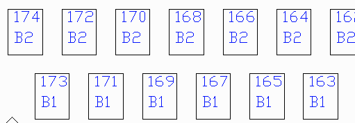
    For staggered die the die pads are numbered in/out. B1 indicates bottom of chip tier 1 and B2 indicates bottom tier 2.


    Die Scribe Outline

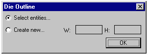
    Sometimes the die scribe outline is present in the GDSII data - in that case the user can select the entity or entities that make up the outline and they will be moved to a special die outline layer.

    However if no outline came in, the user can still specify the height and width of the die and the die clean routine will draw the outline centered around 0,0.

    dc9.gif dc10.gif


    Die Name

    Users may wish to enter a die name that will be placed on the die drawing.

    To do so enter the die name in the dialog box. When you hit OK, you will be prompted to place the name.

    dc11.gif dc12.gif


    Return to:
    WireBond Main Page | Bondmaster Data Browser | Device Image | Device Cleaner

    Artwork Conversion Software, Inc.   417 Ingalls St.   Santa Cruz, CA 95060
    Tel 831.426.6163    email info@artwork.com