
It is important to review and set the preference values so that the NETEX-G output works as expected. The dialog, along with explanations of each feature is shown below:
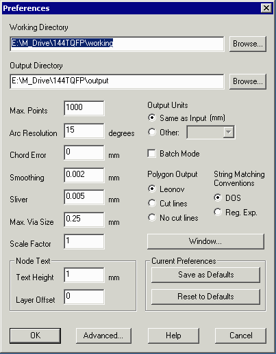
Working Directory - NETEX-G writes all of its intermediate and temporary files to this directory. We suggest that you dedicate a directory just to hold these files so that they can be erased when the project is complete. Quite a few files are generated.
Output Directory - NETEX-G writes any completed output files to this directory: GDSII, DXF, ANF, 3Di or ASCII (depending on the type of output you selected.) We recommend that this be set to a directory holding only the output files and not be the same directory as the Working directory.
Gerber Viewer Path - This points to the location and file name of the GBRVU program executable.
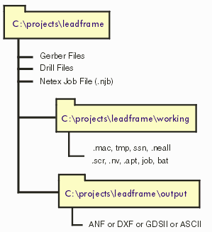
We recommend that under your project directory which contains the input files and the .njb file, you set up two subdirectories: one for the working data and one for the output data.
When NETEX-G creates new geometries the number of vertices can be very large depending on the data it is processing. If your output target database cannot support more than a certain number of vertices per polygon you can specify the maximum allowable vertices here. If NETEX-G sees that an output polygon will have too many vertices it will then "cut" the polygons into smaller pieces as needed.
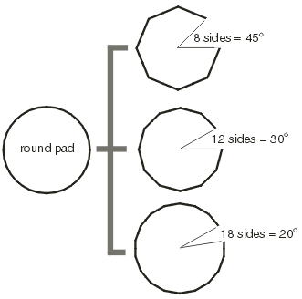
NETEX-G must perform all boolean operations on straight edge data. To do so, it must first convert any arcs or round pads into segments. The Arc resolution parameter controls the number of segments based on the angle that each cord will subtend. Values range from 2 degrees to as much as 45 degrees. It is dangerous however to select very coarse values or the shape of the resulting output may be badly distorted.
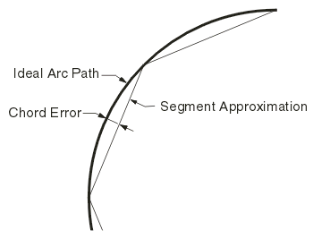
Chord Error is the difference between the ideal arc and the approximation using segments. The number of segments is chosen so that the maximum error (which occurs at the midpoint of each chord) equals the chord error setting. The advantage of using this parameter is that for large radius arcs the number of segments is increased; for small arcs the number of segments is decreased.
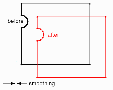
After the Boolean process there are often many closely spaced vertices primarily due to the fact that when round pads are Booleanized they must first be converted into polygons. For finite element applications these closely spaced vertices can be a problem for meshing and analysis. The smoothing function removes vertices that are closely spaced and the parameter entered by the user determines what is considered too close. Remember to enter this in the same units as the input Gerber files: inch or mm.
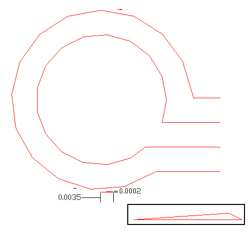
Sometimes during the Boolean operation (primarily when arcs are approximated with line segments) small pieces of isolated metal will be left in the output. These are generally of no interest and can be automatically filtered out if the sliver parameter is set.
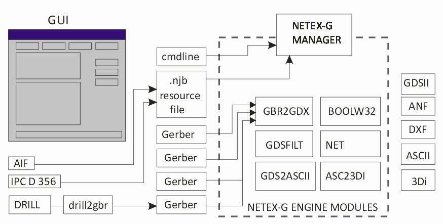
NETEX-G has two components. The user interface and a computation engine. The user interface actually creates required resource files and a command line that launches the computational engine. If you are developing a program that bypasses the GUI and you wish to generate a command line without actually executing the computational engine check this box. You can then examine the command line carefully in order to develop and test your own interface. This is only for programmers.
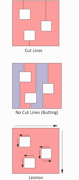
Because the results from NETEX-G are available for different targets, we have implemented 3 different ways of expressing the same polygon data. This applies when the polygons contain "islands" of isolated metal.
Cut Lines - this is a "line" that goes into and out of a polygon and is typically the type of output used for GDSII stream since most IC tools support polygons with cut lines.
No Cut Lines - some CAD systems can't read in polygons that touch themselves. No Cut Lines option actually breaks a polygons with an island into two or more polygons that butt up against each other.
Leonov - Leonov Polygons (named after a Russian mathematician who has written key papers on boolean operations) are actually groups of polygons: an outer parent polygon and a group of inner children polygon. Some CAD systems prefer to represent the islands in this fashion (e.g. Ansoft).
In many cases you may not wish to deal with the entire PCB or package. The Window function allows the user to specify a window, either by entering the coordinates manually, or by using the GBRVU program to enter the window using the mouse. A new feature, recently added, allows a polygonal window which is useful when the area you are looking at has an irregular shape.

The settings in the Preference section are stored in the NETEX-G job file (.njb) but by pressing SAVE you can also save them to the Windows registry. The next time you run NETEX-G the values saved to the registry are automatically loaded.

If you have assigned node labels in your project — normally done by importing either IPC D 356 or AIF files — the labels will appear in certain types of output such as GDSII and DXF.
Text Height - This parameter controls the height of the text. Make sure to enter it in the same units a the input Gerber data.
Layer Offset - Text is placed on its own layer. The layer offset determines the layer. If the labels annotate metal on stackup 5 then the node text for this layer would be 5 + offset.
