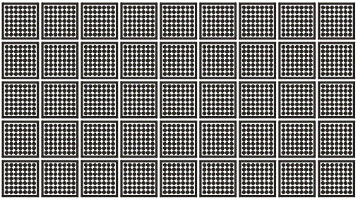

GDS-SR is a step and repeat utility designed to take a die (in GDSII format) and step-and-repeat it to create a whole wafer mask.
The stepping is simple and intuitive and designed to fill in a round wafer with an (optional) flat on the bottom.
In addition to generating the stepped array, there are several advanced functions incorporate into GDS-SR in order to help a designer produce a complete wafer mask ready for the photo mask shop that does not need further intervention or CAD work.
This includes the ability to mix multiple die, to remove die and to replace selected die with special devices for alignment or calibration.
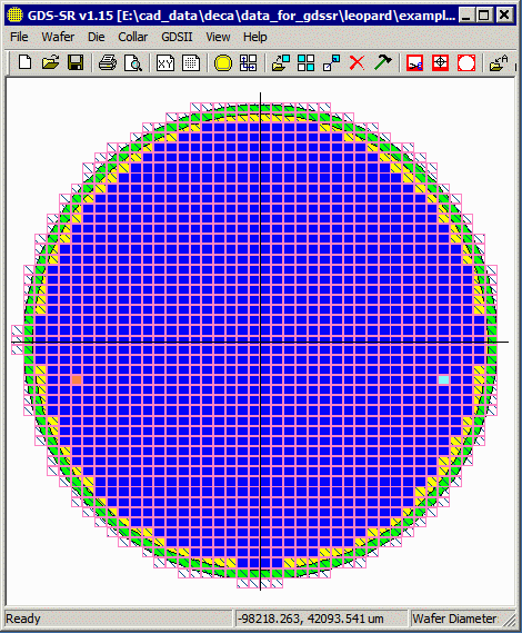
GDS-SR is designed to step a cell over a whole wafer. It can take into account a flat on the one edge of the wafer.
Reticle Input
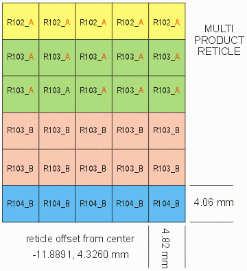
For wafer level masks, the foundry often supplies stepping information of the reticle - GDS-SR can take reticle step information (even with mixed products) and create the required array in only a few mouse clicks. It does all computations necessary to determine which die are inside the wafer. Details ...
Drop In Target and Test Cells
Usually some of the arrayed product die are replaced with alignment die or test die which have the exact same dimensions but with different geometries. GDS-SR allows the user to click on an existing die and replace it with a different device. Details ...
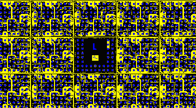
Example of right alignment Die to replace a product die.
Auto-Placement of Alignment Die
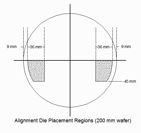
Left and right alignment die can be automatically placed - the location is based on standardized rules...
Automatic Collar Generation
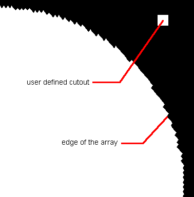
The mask designer often has to create a dark field region which exactly follows the edge of the arrayed die. This can only be done after stepping and is often "hand drawn" The edge becomes extremely difficult to draw if the circuits are small and the array is staggered.
GDS-SR's collar generator uses Boolean operations to find the outer "edge" of the array and produces a dark field polygon out to the edge of the mask.
In addition, the user can define multiple rectangular cutouts that will be filled with targets or mask labels. Details
Automation/Scripting
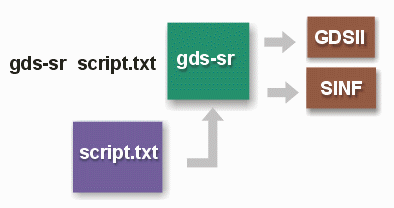
GDS-SR can be run in fully automatic mode by creating a resource file containing the required inputs and directives. Ideal for automation and integration with manufacturing database software.Details ...
Staggered Stepping
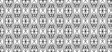
Some MEMs need not be stepped into a rectangular array with a constant street width between circuits. If the parts are separated by chemical etching and the basic cell is not rectangular, then there may be staggered steppings which produce more circuits per square mm of wafer area.
Replace Edge (Margin) Die
This feature examines the arrayed product die and can change them for a different die type if they touch or cross the margin. Some mask designers prefer to use a different mask for edge die. Details ...
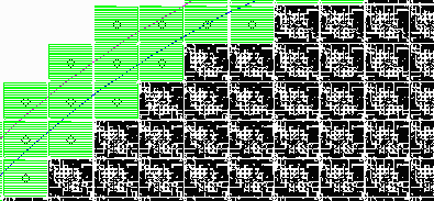
Generate/Display Wafer Fiducials
In order to display the location of wafer fiducials, GDS-SR can read their location from a table and display or output a high resolution bitmap. This is intended for documentation and does not affect the GDSII output. Details ...
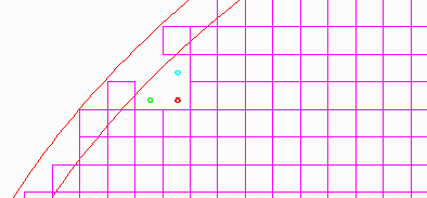
Rectangular Panels
Fan Out Wafer Level Packaging (FOWLP) is transitioning to rectangular panels from round silicon wafers. GDS-SR has a new panel module that supports panel geometries Details ...
