 |
User Defined Wire ModelsAs soon as 3DVU was released, we received requests from various designers for custom wire models. Unfortunately, one cannot create a custom wire model for each designer (especially when the designer is unwilling to provide the model based on proprietary issues.) What to do? Why create a build-it-yourself wire model. This enables each designer to create as many custom wire models as needed and does not require transfer of proprietary information outside of his company. |
||
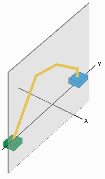
BackgroundCustom wire profiles are constrained by the endpoints of the wires. The 2D layout specifies the starting and ending coordinates in X and Y. The Z values at the endpoints are also constrained by the Z values of the die pad and bond finger or ring to which the wire is attached. The other “known” is based on the assumption that the wire will lie in the vertical plane defined by the start and end points. That leaves us with a series of “points” or bends that the wire passes through as it gets from start to end. |

|
|
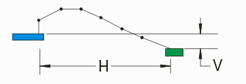
Point to PointOur approach to custom wire profiles is to calculate each new point on the profile from the previous point. Based on wire profiles we have already seen, there are two reasonable ways to calculate the delta:
The illustration below shows different possible combinations for point to point calculations: 

|
3Di SyntaxNow that we have defined how each point can be calculated from the previous point we need to establish a syntax that the dynamic model routine can read. This syntax is based on the syntax already used for the 3Di database. WIRE_MODELS [1] WIRE_MODEL <name> <n_points> <direction> <z1> <z2> [2] <func_type> <param1> <param2> [3] . . SWITCH [4] <func_type> <param1> <param2> [5] [1] The WIRE_MODELS keyword tells the parser that wire models follow. [2] The WIRE_MODEL keyword is followed by a user assigned name and the number of points (vertices) in the wire model including the starting point and the ending point. The direction paramters is either FORWARD or REVERSE depending on whether the function starts at the beginning point of the wire or at the ending point. Z1 and Z2 are the heights at the beginning of the wire and the ending of wire. [3] The third line defines a function for calculating the next point in the wire. Functions are paired (one for X and one for Y.) The available functions are: Hk (horizontal constant), Hm (horizontal multiply), Vk (vertical constant), Vm (vertical multiply) and Ak (angle constant) which can be used with either a horizontal or a vertical partner. There will be exactly N-2 function lines since the first and last point in the profile are fixed in place. Following the function pairs are a pair of parameters which represent either a fixed distance, a multiplier or a fixed angle. [4] The SWITCH keyword tells the wire interpreter to switch from the current point in the profile to the end point. This allows one to work from the end towards the middle of the profile. We only added this to support the "strange" JEDEC preferred model but we don't think that SWITCH will be used very often. [5] If SWITCH is used it will be followed by at least one function line. Examples of Custom Wire Models
|
|||||||||||||||||||||||||||||||||||
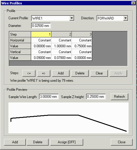
The Wire Profile DialogWire profiles are initially read from the 3Di file but can be added or modified in 3DVU. The Wire Profile Dialog box is shown below: 
|
|||
| 3DVU | 3Di Format Specification |
|
|