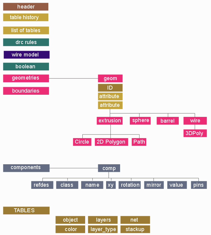
The 3Di format started as a simple description of polygons in the X-Y plane that have a height and thickness attribute. Artwork developed this format as part of the effort to model IC packages and substrates in 3D. We also added property tables that allow one to tag each geometry with useful information: net names, materials, groups and such.
The 3Di file is currently produced by Cadence's SIP program and Artwork's NETEX-G/ODB software and Artwork's AWROut plug-in for Allegro -- but in any PCB, IC or micro-electronic design application can produce this file format and then view or check it using 3D-VU. We are documenting this format in case others who wish to develop 3D IC packaging tools would like to use this sd s building block.

Click on any block in the image to get more details.
The first section in the 3Di file should be the header where the version is specified along with the units/resolution. This section is mandatory since without units information the rest of the data is meaningless.
3Di <version> <units> <precision>
Example
3Di 2.2.1 microns 2
Describes the tools that produced this file. This section is optional. Often more than one tool is used to generate the final output. For example, when exporting from Cadence when the user has specified a data window the initial 3Di file exported is then "clipped" using the 3DiBool program.
<index> <product_name> <product_version> <write_date>
Example
TABLE HISTORY

1 Cadence 3D Design Viewer v16.6.1 [August 9, 2011 12:56:54]

2 3DiBool v1.10 [August 9, 2011 12:57:02]
A directive that tells the 3DiBool program how to clip this file. It is generally not necessary for a 3Di parser to be able to read or otherwise interpret this section.
BOOLEAN
BOOL <number> <name>
CLIP <n_points>
<x1> <y1> ... <xn> <yn>
BOOL <number> <name>
SIZE <sizing_value> <table> <index>
BOOL <number> <name>
ARCS <arc_sag>
Example
BOOLEAN
BOOL 1 Sample Clipping      operation, ID and name
CLIP 4                      clip with 4 vertices (autoclosing)
100.0 100.0                 x,y
300.0 100.0                 x,y
100.0 200.0                 x,y
100.0 200.0                 x,y
BOOL 2 Sample Sizing        operation, ID, and name
SIZE 5.0 NET 57             size up by 5.0 mils all members of table NET, index 57
Tables are used when it is more efficient to list values in the table and then refer to them by an index. In order to use tables effectively it is necessary to list the table names before any tables are populated or references are made in the geometry section. There are a number of "standard" tables that 3Di uses and they are listed in the example below. Additional tables can be defined and used since a proper 3Di reader will ignore any table entries it does not understand.
Not all the standard tables shown below will always be present because their existence depends both on the source of the data and the specific 3Di generator.
TABLE <name>
Example
TABLE OBJECT        typically object attribute such as pin, via, trace, pad, shape

TABLE LAYER         typically the source layer name such as M1, VIA12

TABLE LAYER_TYPE    typically an attribute such as conductor, dielectric

TABLE COLOR         an RGB value (0-255) or RGBA where A=transparency

TABLE NET           the net name associated with a conducting element

TABLE NET_PINS      a pin number or label associated with a net index

TABLE STACK-UP      similar to layer but related to a stack up

TABLE WIRE_MODEL    if wires are present, wire models are defined this could be used

TABLE CONNECT       if connection data was extracted the ID of each element could be put here
The 3DVU program has an optional DRC rule checking module. A user can define a number of rules that check clearances: wire to wire, body to body and wire to body. These rules can be saved in the 3Di database.
In most cases this section will be empty unless a user opened the 3Di file in 3DVU, defined rules, and then saved the file.
DRC_RULES
RULE <number> <name>
[IGNORE_SAME_NET YES]
<type> <n_inputs> <parameters>
GEOM
<table> <index>
.
.
GEOM
<table> <index>
.
<marker>
Example
DRC_RULES
RULE 1 Wire-Wire Spacing Rule
SPAC 2 25.000000               space rule with 2 inputs and 25 um spacing
GEOM                           first item is a geometry of OBJECT 6 (obviously a wire)
OBJECT 6
GEOM                           second item is a geomety of OBJECT 6 (another wire)
OBJECT 6
GEOM                           the marker is a geometry with COLOR=30 and is a sphere
COLOR 30
SPHE 0.0 0.0 0.0 50.0 12
Bond wires are defined in the geometry section by the wire endpoints. The path that the wire follows is derived from a wire model or profile. More information can be found on the page: Custom Wire Models.
WIRE_MODELS
WIRE_MODEL <number>
<name> <radius> <points> <direction>
STEP
HOR [X] | ANG <value>
[TURN <value>]
VER [X] | ANG <value>
.
.
STEP
.
SWITCH
.
STEP
.
Example
WIRE_MODELS
WIRE_MODEL 1
PROFILE 1 12.500000 4 FORWARD
STEP
HOR 0.000000
VER X 0.250000
STEP
HOR 500.000000
VER X 0.000000

JEDEC_5P 12.700000 5 FORWARD
STEP
ANG 85.000000
VER 250.000000
STEP
HOR X 0.125000
VER -50.000000
SWITCH
STEP
HOR X 0.500000
TURN 5.000000
ANG 5.000000
A directive used primarily by Artwork's engine that converts from 3Di into either STEP/parasolids. It is used to define cutouts routed into the PCB. These cutouts run from the very top to the very bottom of the design.
BOUNDARIES
BOUNDARY
TYPE <type>                       only type supported = DIELECTRIC
COUNT <n_children>                parent poly plus all children (cutouts)
2DPG <n_points>                   2D polygon
<x1> <y1> ... <xn> <yn>
Example
BOUNDARIES

BOUNDARY
TYPE DIELECTRIC
COUNT 5                           this boundary has total 5 polygons
2DPG 65                           first polygon is always the "parent"
-0.097929 -0.393858
0.121863 -0.393858
0.129469 -0.392346
.
.
-0.097929 -0.393858
2DPG 17                           child or "cutout" polygon
-0.116000 0.246409
-0.125793 0.248357
.
.
-0.116000 0.246409
2DPG 24
-0.095395 -0.359758
-0.104464 -0.357996
.
.
-0.086226 -0.358632
-0.095395 -0.359758
2DPG 17
0.085000 -0.346590
.
.
2DPG 17
0.113000 0.318472
0.101700 0.320720
The next section of the 3Di file is the GEOMETRY section.