Creating the Command Line, List Files and Response Files
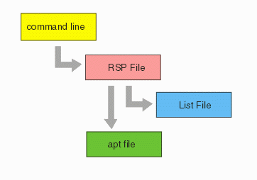
The dxf2gbr engine is called via a command line. Because of the large number of layers and arguments, the command line references a response file which in turn . So prior to calling the dxf2gbr engine the calling application must create the response and list files.

Command Line
a2g501.exe "@c:\test\ac2000.rsp" 0
atg501.exe is the name of the ASM501 dxf2gbr engine. The @ sign indicates that what follows is a response file. The path and file name should be quoted so that spaces in the path do not cause problems.
Response File
The response file contains most of the command line arguments and also points to a list file (.lst) that specifies a list of layers to process. The response file is one long line but here the individual elements of the line are broken out for documentation purposes.
"C:\test\ac2000.dxf"                 the fully qualified name (i.e. with path)
                                     of the DXF file. Should be quoted.


MM                                    units of the DXF file.
                                      Valid options are: INCH, MM, MIL, UM.


0.0001                                input database resolution.


"@C:\test\xx.lst"                     name of the list file that contains the list
                                      of the layers to convert to Gerber.


1.0                                   scale factor

-d                                    optional - use to suppress dimensions. If you want
                                      to convert dimensions remove this argument.


-nlnk                                 linking of lines into closed polylines. ASM 501 does
                                      not support linking so this option is always -nlnk


-t0                                   -t = trace mode. Options are = 0, 1, 2  Determines
                                      how constant width polylines are converted to Gerber.


-on10,10                              -on = outline mode. If present, then items such as
                                      polylines with  width are outlined instead of mapped to
                                      a matching d-code. The two numbers that follow are d-codes
                                      used for outlining. Typically they are the same value
                                      i.e. D15 would be 15,15.


-c:0                                  compensation (this should always be set to 0)


"-cfg:C:\test\ac2000.apt"             points to the name/location of the aperture list.
The LST File
This LST which is referenced by the response file contains a list of layers to convert. Since each layer will produce its own Gerber file the list also includes the output Gerber file name. A .lst file is shown below:
"0"      "C:\test\0.gbr"
"DIM"   "C:\test\DIM.GBR"
"gaso1" "C:\test\gaso1.GBR"
column1 - the AutoCAD layer name. The name should be quoted since AutoCAD recently has allowed the use of spaces in the layer name.
column 2 - the name of the Gerber file to produce. This should be a fully qualified path and should be quoted so that spaces in the directory or file names will be properly interpreted.