Generating a Layout from Shot Map Parameters
In order get a precisely placed layout relative to the wafer's center we will use the same shot map parameters used to step out the wafer's die.
The Shot Map Parameters
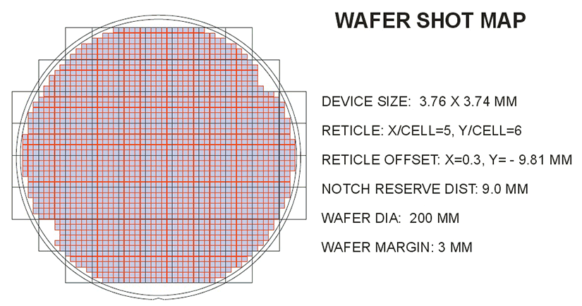
In most cases the package designer will get a list of parameters or even a screen shot that looks something like this:

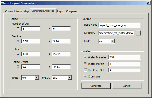
Select the middle tab and enter these parameters into the appropriate field. Make sure to turn on the "graphics" elements because they are necessary to properly clip the shot map data to the extents of the wafer.

Now click on the Generate button.
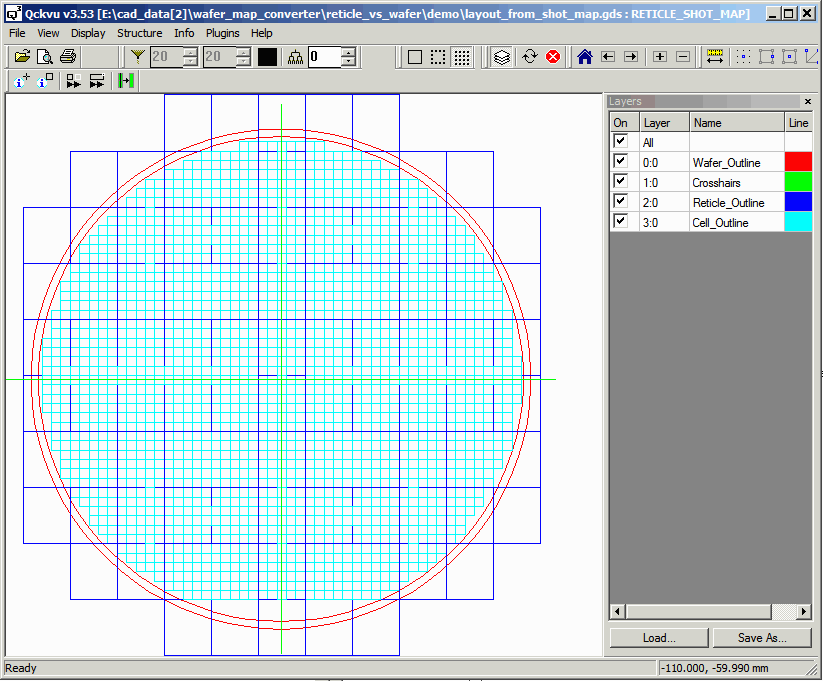
You should see something like the screen below in the Qckvu3 display window:

Now this layout has the die correctly located relative to the wafer center. On the other hand, it does not contain information about any special alignment or test die or any knocked out regions. That information is contained in the layout generated from the wafer map.
In the next step we are going to place one layout over the other -- we should be able to easily measure the offset. That will tell us how much we need to "move" the layout generated from the wafer map.
Next -- Comparing Position of Layout from Wafer Map and Shot Map
