Automatic Finger Synthesis and Placement
Once you have imported or synthesized your die, FA4ST can create the bond fingers needed to connect from die to package. FA4ST helps you quickly decide on finger spacing, number of tiers and distance from the rings.
One of FA4ST's nicest feature is that it quickly tells you how many IO's are on each side of the die - you specify which nets are downbonded (we assume these are power and grounds) and the rest are IO.
There are two versions of this dialog - one for designs with rings and one for designs with no-rings (i.e die only)
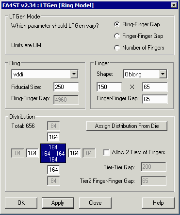
The user can have LTGen solve for either: the die-to-finger gap (i.e the wire length), finger-to-finger gap or or the number of fingers.
Ring Finger Gap - if you are solving for finger spacing or for number of fingers specify the shortest allowable gap. If solving for ring-finger gap this field is grayed out.
Fiducial Size - if specified a square "fiducial" is placed at each corner of the die aligned with the fingers. This can be used to put an alignment target and keeps fingers out of this region.
Finger Shape - specify fingers to be rectangular or oblong or open ended (for leadframes); then specify the width and length.
Finger-Finger Gap - the minimum spacing between fingers.
Distribution - if you are solving for gap or distance, specify the number of fingers on each side of the die. If you are solving for number of fingers the program will report the number here.
Assign Distribution from Die - opens a dialog that enables you to specify nets for ring attach - effectively removing them from the IO count.
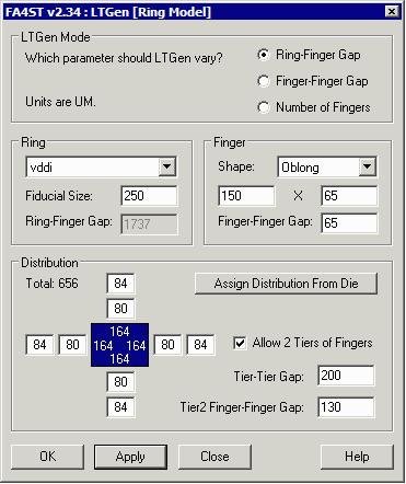
Allow 2 Tiers ... - tells LTGen it can use two tiers of bond fingers if needed to accomodate all of the fingers. In that case you must specify two more parameters:
Tier-Tier Gap - space between the bondfinger tiers.
Tier2 Finger-Finger Gap - the finger gap for the second row of fingers.

In the example we have a large dense die with 764 die pads on each side - 656 of them (164 on each side) go to fingers and the balance are bonded to rings. We've asked LTGen to solve for the "ring-bondfinger" gap (which is essentially the wire length) given our finger width/spacing and the need for 164 bond fingers on each side of the die.
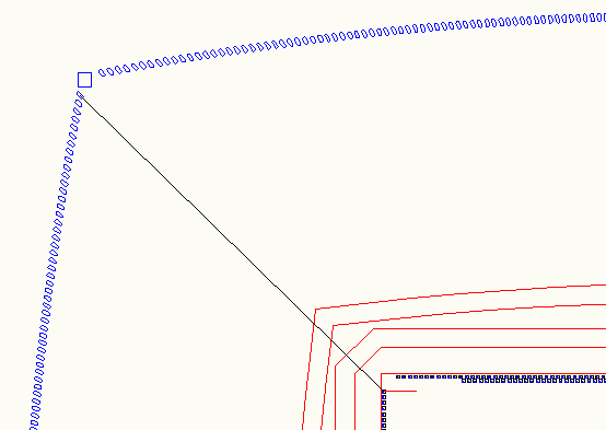
We had already synthesized the ground and power rings based on our standard design rules. The results are shown below:

I measured the corner wire length and immediately noticed that this wire is 7900 um when in fact my design rules state no more than 4500 um. Clearly the a single row of fingers cannot be used as the maximum wire length needed (to keep the mininum finger spacing) is way too large.
Reducing the Max Wire Length
The only way to reduce the maximum wire length to an acceptable level is to use two rows of bond fingers. This generates another complication -- bondwire crossing. In order to make sure the part is buildable we have to make sure that wires in the outer row of die pads go to the inner row of fingers and wires in the inner row of die pads fly over to the outer row of fingers. To generate the fingers we have to know how many IO's are in the outer and inner rows of die pads.
Fortunately, LTGen's special function, Assign from Die, allows you to specify the power/ground nets and to remove those from the IO count. It also then chooses for you the finger count for each row.

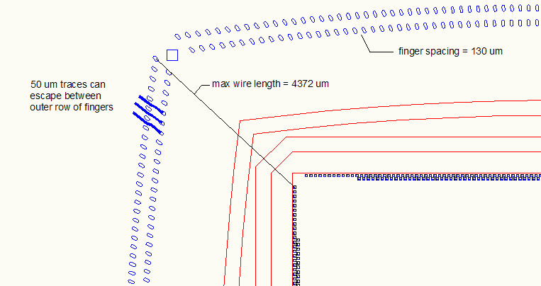
I actually made several iterations by changing the finger spacing in the outer row. While my design rules allow me to space fingers as tight as 65 um, I would have liked to space the outer row of fingers by about 150 um to allow a 50 um route to pass between fingers. However I could not get the full 150um spacing and still keep under a 4500 um max wire length -- but I was able to quickly try different values until compromising at 130 um finger spacing and 4370 um max wire length.

