APD Import Web Page Header


Wire Builder

Once you have created your shapes and built your two symbols, you need to run the Wire Builder routine in order to identify the wires.

This will enable the program to build a net list connecting the die symbol to the package symbol. Note that die to die and package to package bonds are supported.
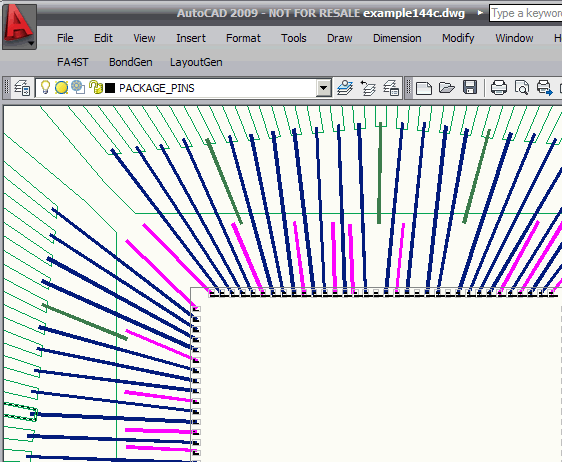
  The Wire Builder associates wires with die pads or conductors

The Wire Builder associated the wire endpoints with pads or conductors


How It Works

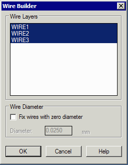
First, make sure you have already built your shapes (i.e. leadframe conductors) and symbols. Then start the Wire Builder ... from the LayoutGen drop down menu. A dialog will appear as shown:

You will be presented with a list of layers that may or may not contain wires. Highlight all of the layers that contain wires. Hold the Ctrl key down to highlight multiple layers. (Generally one should attempt to isolate wires by tiers on their own layers -- this could be useful later on)

If your wires were drawn using lines instead of a polyline with width, you can assign a default diameter to the wire.


wire builder dialog


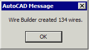
The program will run very quickly and report on the number of wires processed.

  number of wires processed


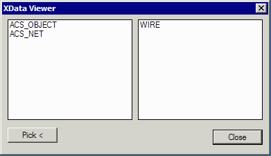
You can verify that a pline was recognized as a wire by using the utility Xdata Viewer. Start the Xdata Viewer and click on Pick. Then click on a polyline that you think should be a wire.

  the Xdata Viewer shows the pline has a WIRE object property.