APD Import Web Page Header


Pin Builder

The Pin Builder module automatically creates a rectangular pin for each lead on the periphery of the package. These pins will be needed later when we build the package symbol. In order to import our data into APD we need both a die symbol (created from the die pads) and a package symbol. However lead frames drawn in AutoCAD have no actual symbol pad where they terminate so we need to create one.

Sure we could draw the pins in by hand (using a zero width closed polyline) but there are 144 pins to draw and place. The pin builder does this for us.
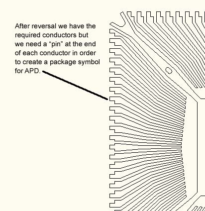
  leadframe before pins placed at periphery of package.

A pin will be needed at the end of each lead.


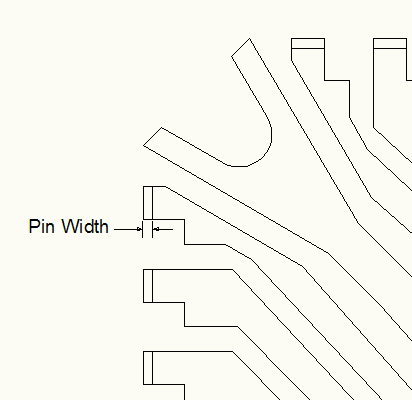
Pin Dimensions - You will be prompted to enter the "width" of the pin. This is actually equal to the thickness of the lead frame metal. The other dimension of the pin is equal to the lead width.

  pin width and positioning.

pin width and positioning


Selecting the Leads

You will be prompted to select the leads (right, top, left, right). Drag the cursor in a windowing motion and be sure to select all of the leads on a side in one selection as you won't be able to use a second selection to select additional leads.

Selecting the Destination

You will also be able to select the destination layer.

Notes:

The pin builder only creates zero width closed polylines. This means that you are free to copy or edit these pins as needed prior to running the symbol builder.

Do not move a pin outside of package periphery. APD does not allow any pins outside of the extents of the symbol outline.

  selecting the leads on the right side of the package

selecting leads on the right side


How It Works

To see a short video demo click below:


pin builder demo

Click to Watch Video