
This program reads Artwork's 3Di format (also the 3Di exported by Cadence SIP) and converts it to STEP. 3Di2STEP can be called by 3DVU as a menu selection or it can be run standalone if you need something that is scriptable.
STEP can be imported into a wide range of 3D CAD tools such as SOLIDWORKS, AutoDesk Inventor, Creo, PTC, Catia, Solid Edge and others. The translator can be launched from a menu within 3DVU or run as a stand alone translator.
The simple one, FFF (Form, Fit, Function) outputs a fairly straightforward conversion of our 3Di database and is sutiable for when you are using the STEP to create visualizations of your PCB or when you are trying to insure it fits into its case or housing.
We found that STEP that is to be used for FEA simulations needs additional processing. FEA meshers are very sensitive to things like internal collisions between solid bodies, mating faces between bodies and data complexity -- too many vertices results in too may mesh faces and the simulation bogs down or even fails.
(Simple FFF Version of STEP - to see the FEA version go here ...)
Open a 3Di file using 3DVU.
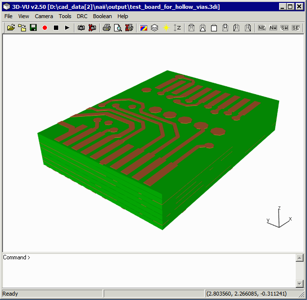
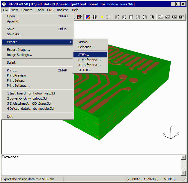
Click on File | Export | STEP ... to launch the STEP export dialog.
The Export STEP dialog will appear.
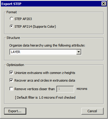
Dialog Options
Format - choose between AP 203 and AP 214. AP 214 support color attributes. You would only need AP203 for very old 3D tools that don't support AP214.
Structure
Organize - this drop down enables the user to output the data with different organizations. The default is by layer - each conductor layer, drill layer and substrate layer is placed into a "part" and the parts are then instanced into an assembly.
The other useful organization option is by NET. In this case, all members of a net (conductors) are placed into a single part. This makes it easy for the 3D user to select all solid bodies belonging to a single net.
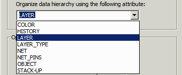
As you can see there are a number of attributes that you can use to organize the STEP output - however we have only found NET and LAYER to be useful.
Optimization
There are several optimizations that can be performed during the export conversion.
a) Unionize extrusions with a common Z-height. If there are interfering bodies in a given conductor plane, this will combine those bodies into a single body. We recommend that you enable this as some STEP importers or simulation tools will crash if they get interfering solid bodies.
b) Recover Arcs and Circles in Extrusion Data - when the source data is a PCB there are intially a large number of arcs due to the round pads and round bends in the traces. These are "lost" during the Boolean operations. They can be recovered (assuming the approximation is smooth enough) and output as arcs to STEP. This can greatly reduce the size of the STEP file. Some simulation tools work best with arcs and some don't.
b) Remove Vertices Closer Than - When the source data contained very closely spaced vertices some 3D tools have a problem processing the STEP data. If you check this box and enter a value the program will search for closely spaced vertices and delete one of them. Note that this might also "distort" the data in some way so we don't recommend setting it on unless you have run into problems without it.
Note that STEP files are very very large relative to the actual geometric content that they contain.
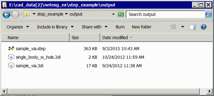
While 3Di2STEP is normally launched from the 3DVU program, one can also run the 3Di to STEP translator from a command line.
The command line syntax is:
3Di2STEP.exe  -h          displays the command line arguments

or

3Di2STEP.exe -version     displays the version of 3Di2STEP

or


3Di2STEP input_file.3di   output_file.step [options]

where options are:


3Di2STEP (standard version options)
-----------------------------------

 -unionize                 Unionize extrusions that share a common Z height

 -arcs                     Recover arcs from extrusions

 -ap214                    Generate STEP AP214 (instead of STEP AP203)

 -hierarchy:attribute      Build a hierarchical STEP file using the specified attribute
                           (LAYER or NET)

 -vertex_filter:value      removes closely spaced vertices. Default = 1 (um). Can be
                           set lower if your 3D importer supports very closely space
                           vertices.

 -units:<units>            Convert into the the specified units


3DiSTEP for FEA (advanced options)
----------------------------------

 -alternate:attribute      Alternate attribute used to build a hierarchical STEP file

 -via_sort                 Build additional hierarchy based on via size

 -via_merge                merge all via parts (i.e. from layers) which share the
                           same ID into a single cylinder.

 -remove_pins              remove duplicate geometries generated by PIN data

 -expand_dielectric:<d>    Expand dielectric bounding box by "d" on all sides - needed
                           if you invoke the negative_dielectric function to prevent
                           Boolean problems at the board periphery.

 -negative_dielectric      generate "negative" dielectric on the conductor layers to
                           simulate the flow of dielectric into these gaps.

 -viasides:sides           Replace circular vias with low resolution polygons

 -via_drills               add holes to conductors and dielectrics where the via
                           passes through them to avoid interfering bodies.


 -viawall:<thickness>      Add drill holes to vias using the specified wall thickness

 -via_plugs                Add a via plug cylinder to the interior of the via. (Only use
                           together with -viawall.
This short video tutorial (02:22) shows how quickly one can go from 3Di into AutoCAD Inventor.
View directly on Vimeo: https://vimeo.com/124437243.