page header


[RINGS]

The RINGS section is used to describe metal on the bonding layer. We call it RINGS but in fact it can be used to define any metal on the bonding layer and even non-metal geometries. Generally, the RINGS section is not "hand" created from a spreadsheet but generated by a CAD translation or extraction program.

Basic Syntax

[RINGS]
NAME NET_NAME NUMBER_OF_POLYGONS WIDTH NUM_OF_VERTICES
X,Y
X,Y
X,Y
NUM_OF_VERTICES
X,Y
X,Y
X,Y

NAME - each ring entity must be assigned a name. No special use is made of names by the AIF parser but a user could make special use of the name.

NET_NAME - assuming the ring is a conductor, it should have a valid net name. If a ring is "not" a conductor, then some sort of placeholder name should be used i.e. DUMMY.

NUMBER_OF_POLYGONS - If this piece of the ring is a simple closed region it will consist of one polygon. However if it contains "cutouts" then there might be more than one polygon.

WIDTH - for a region the width = 0. However one could represent a trace using a finite width.

NUM_OF_VERTICES - the number of vertices (for this polygon) to follow. This makes life simpler for a parser. Note: if the number of vertices is expressed as a negative number, i.e. -25, this tells the parser that this is a cutout polygon and should be treated appropriately.

X,Y - coordinates of a vertex. There are no arcs in the RING definition. It is not necessary to limit a single pair of vertices per line but it makes the file more readable to do so.


Multiple Rings with Cutouts

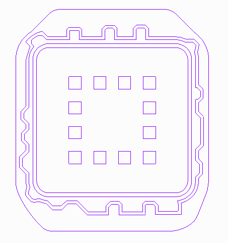
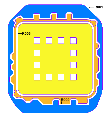
This example shows a fairly complicated ring design for a large BGA. There are three rings - the outer VSS2, the middle VDD and the inner VSS1 ring. The outer ring is built from two polygons - the parent and a single cutout as is the middle ring. The inner ring is built from 13 polys - one outer and 12 cutouts. This is easier to see when the rings are colored below:

  example of multiple rings with cutouts


Notice that ring R003 has multiple square cutouts.

  example of multiple rings with cutouts


Here are some fragments of the RING definition that generates these figures:


[RINGS]
R001 VSS2 2 0 77            <-- ring R001; net VSS2 with 2 polygons
4830.460000, -3717.840000   <-- vertices for outer ring
4463.680000, -4654.470000
4389.530511, -4826.829327

4830.460000, -3717.840000
-228                        <-- 228 vertices in cutout polygon
-3726.610000, -4162.070000
-4011.950000, -4193.390000

-3716.880000, -4166.280000
-3726.610000, -4162.070000  <-- last vertex in cutout end of R001
R002 VDD 2 0 203            <-- ring R002; net VDD 2 polygons
3417.410000, -4105.660000   <-- vertices for outer part
3344.260000, -4126.180000

3417.410000, -4105.640000
3417.410000, -4105.660000
-49                         <-- cutout has 49 vertices
3247.840000, -3913.500000
-3247.840000, -3913.500000
R003 VSS1 13 0 41           <-- ring R003; net VSS1 13 polygons
-3247.840000, -3713.400000
-3357.238352, -3703.828884

-5                          <-- note square has 5 vertices
-2222.500000, 1587.500000
-1587.500000, 1587.500000
-1587.500000, 2222.500000
-2222.500000, 2222.500000
-2222.500000, 1587.500000   <-- last & first vertex are same