
|
|
Related Topics: |
Converting Gerber Data into Wire EndpointsConverting Gerber data into intelligent wire data is not as straightforward as it seems particularily when the target output is Ansoft's ANF file format. It is not a simple matter of finding the endpoints of each wire. To understand why, you must know something about the Ansoft Neutral file architecture. 
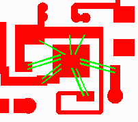
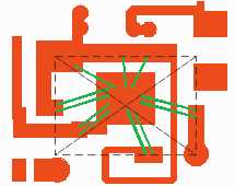
Ansoft requires on one end of the wire a "fake" via that connects it to the metal below. The other end wire hangs "free" and is assumed to go to the die pad. While this seems like a reasonable approach it requires that NETEX-G somehow take each Gerber draw command and figure out which end goes to the die and which end goes to the metal. Once we've decided that we drop down a "fake" via to the metal side of the wire. The screen shot above shows a typical RF circuit where wires connect the device to the substrate. The Gerber data that represents the wires gives us no clue as to which end belongs to the die pads and which end goes to the substrate. Should we "guess" wrong all of the wires will be shorted out to the die paddle. Finding the Die Side of the Wires To find the die side of the wires we collect all the endpoints and create a "bounding box" defining the outer limits of the wires. It is then easy to find the center of this box. 
Once the "center" is known, the endpoint of the wire closest to the center is defined to be the die side. This assumption is pretty safe for most designs but it can fail under some conditions. |
|
Download |
Benchmark Files |
Revision History |
Price |