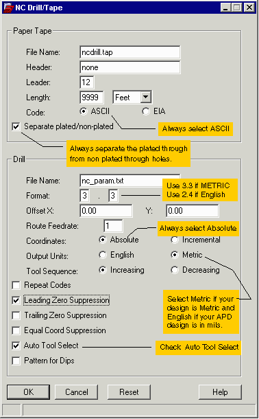
The NC Drill Parameter
There are some things you can do when producing the Drill Tape from APD that will make the file a bit more usable for the rest of the world though it involves much user intervention.
Paper Tape
File Name: Enter the file name you wish to create here.
Header, Leader and Length - don't care
Code - ASCII
Plated/Non Plated - always check this -- you don't want plated and non-plated holes in the same drill file.
Drill
File Name - this is the default parameter file name. Leave it at nc_param.txt.Format - if your units are metric, use 3.3. If English (inches) use 2.4.
Offset - leave it a 0,0. Otherwise your Gerber data and Drill data might not line up.
Route Feedrate - don't care
Coordinates - either will work but we recommend Absolute.
Output Units - APD always defaults to English. Doesn't make sense if your design is in microns or mm. Select metric if your design is in metric units.
Tool Sequence - don't care
Repeat Codes - don't use it, some CAM stations don't read it.
Leading Zero Suppression - check it.
Trailing Zero Suppression - don't check it.
Equal Coordinate Suppression - if you check it the data file is smaller but harder to read.
Auto Tool Select - Check it. You will then have to create the nc_tools.txt
file or APD will generate an error upon attempting to output a drill file.
Pattern for DIPs - don't check it.

The nc_tools.txt File
The Auto Tool Select Option is needed to produce a proper drill file but APD forces the user to do most of the heavy lifting. You will need to create and edit a file called nc_tools.txt that contains the following information:
Tool Diameter P Tool Change Command
First you must figure out manually which drill hole sizes need to be defined in this table. To do this open you list of padstacks and check each stack to see whether it generates a plated through hole. If so, note down the diameter of the via hole (the units of the hole must match the design units -- not the drill file units ...)
Example - in my design I have a padstack called VIA350 that has a 200 um diameter plated through hole. I also have a second via called VIA100 that has a 30 um plated through hole. My nc_tools.txt file would look like:
200 P T01C0.200
30  P T02C0.030
Be careful. The first entry is the diameter in the design units (for example microns for a typical IC package) but the third column must show the diamter in the drill file units (either mm or inch.).