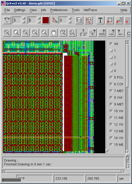
Nettrace Page Header

Qckvu3 Net Trace Plug In

When debugging a chip (say in the failure analysis laboratory) one often uses a FIB to probe various ports on a suspect gate. It is often useful to know where such a port is connected to the rest of the circuitry particularly if access to that port is obscured.

Qckvu3's NetTrace plugin can highlight all conductor elements that are physically touching or connected with vias.

Starting Point

One starts with a layout database in either GDSII or OASIS format along with a list of GDSII layers and their equivalents. In the examples shown below we are using a test file called azuma.gds and it has the following layers of interest:

GDSII Layer      Process Layer
  13:0             POLY
  15:0             CONTACT
  16:0             M1
  17:0             VIA12
  18:0             M2
  27:0             VIA23
  28:0             M3
  29:0             VIA34
  31:0             M4

The convention is to start at POLY/CONTACT and then work up through the various metal layers.

Load the Layout Database

Load the Layout Database and either load a "map" file or mark up the layer list to include the process layer names as this will make setting up the stackup much easier.

The click on the NetTrace Menu item and select: Configuration.
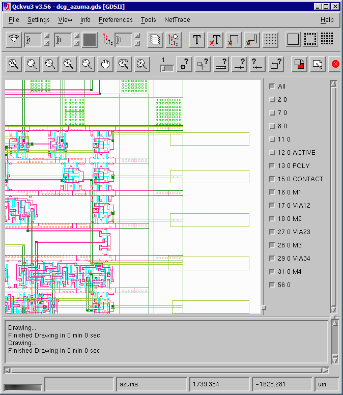
Qckvu3 with azuma loaded ...


The NetTrace Dialog

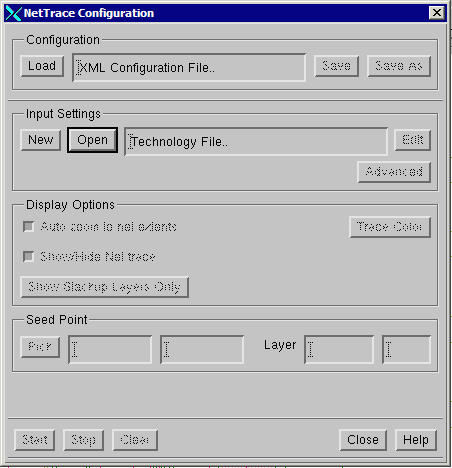
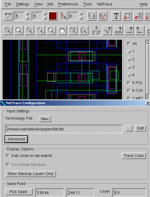
The NetTrace dialog box enables the user to both configure the tracing rules and to control tracing of nets.

NetTrace Dialog


Creating a Tech file

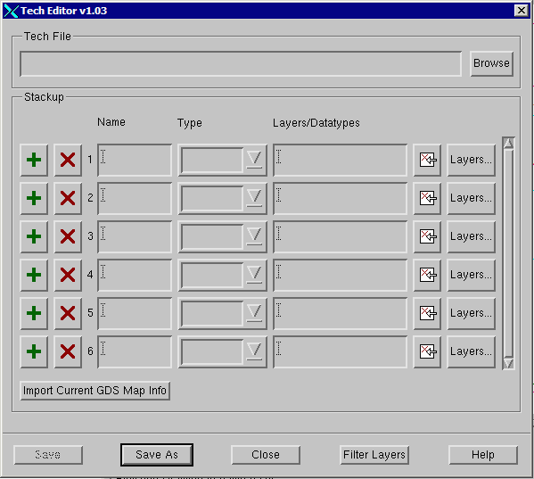
The first step required is to either load an existing technology file or to create a new one. In this example we will create a new one. Under the Input Settings section, click on the NEW button. You should now see the empty tech Editor dialog box.

Tech File Editor Dialog

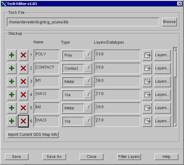
To add a layer to the tech file click on the green "+" sign. The assign the layer a process name such as POLY and a type from the drop down (also POLY) and then enter the GDSII layer:datatype that represents poly.

Then repeat for the CONTACT layer, Metal 1 layer, Via1 layer, Metal 2 layer and so on until you have got to the top of your metal layers.

When you are done, your dialog should look like this:

Tech File Editor Dialog Filled In

Save your tech file to disk. In this example we saved is as dcg_azuma.tlib. You can then reload it at a subsequent session as needed.


Advanced Input Settings

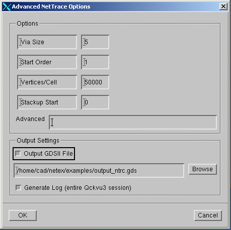
This dialog controls some of the more advanced settings for the net tracing module.

Qckvu3 NetTrace Advanced menu

Options

    Via Size - Maximum possible via size. Any geometries with extents larger than this value will be ignored.

    Start order - Directs Nettrace to start building the net from this layer stackup position. Default is 1.

    Vertices/Cell - Maximum number of vertices per cell (net). This limits (i.e. stops) Nettrace in the case that you select a very large complex net such as VCC or GND.

    Advanced - allows the user to enter command line options for the nettrace engine. This is normally only used by the programmers for debugging purposes.

Output Settings

    Stack up Start - Antonio or Viraj need to document this setting.

    Output GDSII File - Defines the GDSII output file name of the exported output file. Each cell in the output file will be a net.

    Generate Log File - Saves log file to disk


Display Options

This section determines how Nettrace displays the nets.

Nettrace Display Options

    Trace Color - User selects the net highlight color.

    Auto Zoom - When selected, Qckvu3 will always zoom to the extents of the net.

    Show Stackup Layers Only - Turns of layer display except for layers defined in the stackup.


Running a Net Trace

To run a net trace one first must pick a seed point on a particular layer. You can only pick seed points on metal and poly layers -- not on via or contact. Normally seed points are picked using the mouse on the display.


Qckvu3 NetTrace Pick Seed

The last step is to select the start point and layer from which to start building the nets.
The user should first zoom to the polygon of interest and then click on the Pick Seed option.
At this point, click/release/and drag to make a window around the seed point.
The X and Y coordinates along with the layer of the selected object will get updated in the Net trace menu.

Select Seed Point


Highlighted Net

After pressing the Start button, the program will start to build the net.
The net will be highlighted while it is being built and once complete, you will see a message to that effect.
The net will also get saved as a GDSII file under the file name defined by the user.

Highlighted Net


  Download Revision History Linux Install Price