Qckvu3 Web Page Header

Debugging Requires Knowledge of Driver Location

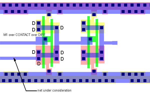
An engineer in the failure analysis laboratory has generally highlighted a net because there is some sort of temperature or radiation anomaly physically detected by a camera or probe in the same region as the net. In order to convert this location into a circuit component and pin identification he often needs to know where the driver is located on the net as there many be many component and pin connections on the net. Nettrace can speed up this identification by doing a fairly simple computation. The computation consists of searching for all coordinates on the net where M1 is located over CONTACT and over DIFF.
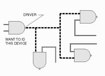


The yield engineer often needs to located the driver on a net where a hotspot has been found


Metal over Contact over Diffusion

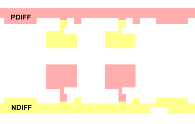
The basic building block in digital IC’s is a pair of stacked FETs whose output are hooked together. This is built by first creating your diffusion regions. Two different diffusions are performed - a NDIFF (for N channel FETS) and a PDIFF (for P channel FETS).

  a regions of P and N diffusion are created.


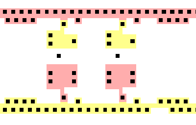
Then openings in the insulating layer above the diffusions are created to form contacts to the diffusion.

  contacts are opened over the diffusion regions.


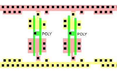
Polysilicon is deposited next. It forms the gate of a FET where it lies over the diffusion regions.

  poly is now deposited. It creates a gate where it lies over the diffusion.


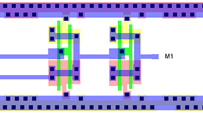
Metal layer 1 is now deposited.

  metal 1 is deposited.


By performing a boolean (actually many times as needed) one can detect all the regions on the net where M1 is found over a contact and also over either a PDIFF or NDIFF area. These are the source or drain connections and are driver outputs.

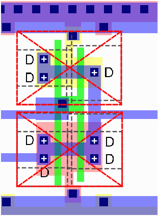
  driver showing where M1 contacts to Diffusion.


Merging Multiple Contacts for a Single Driver

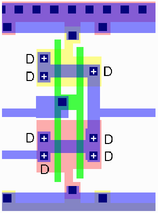
You can see that this driver consists of a stacked P and N device. There are a total of 7 locations where we identify the combination of M1|CONTACT|DIFF. But if this many locations were highlighted in a large design the display would be unecessarily confusing.

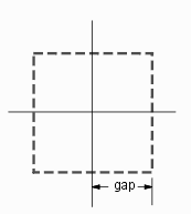
To address this we will define a "gap" value that generates a box around the center of each region.

bounding box size defined by gap parameter
  seven contacts will be highlighted for this driver


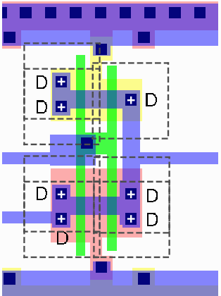
A box is drawn around each of the seven contact locations.

  boxes are drawn around each contact


Overlapping or touching boxes are merged and a bounding box is generated. In this case, the choice of the gap parameter generated two bounding boxes but a slightly larger value would produce a single bounding box and hence a single highlight for the driver.

  bounding boxes from merged boxes ...


Page   Contents
1   Introduction
2   Configuring NetTrace