Steve DiBartolomeo
Applications Manager
Artwork Conversion Software, Inc.
Steve DiBartolomeo
(831) 426-6163
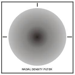
The need to convert a “bitmapped” image to GDSII often arises when producing optical filters where the density is a function of x,y position on the filter.
For example, one may need to build a filter whose density decreases with distance from the center:
density = f ( r-r0 )

Such an image could easily be rendered on a imagsetter similar to those used to make film for magazines - but the resolution might not be enough for laboratory quality since the smallest spot these imagesetters produce is about 10 um.
By using an eBeam or high resolution laserwriter one can easily get pixels in the 1/2 to 1/4 um range.
A grey scale filter is one whose density at any location can have a range of values: typically 256 steps from completely opaque (black) to completely clear. Since most mask making machines are designed to put down a high contrast spot, one must approximate the grey scale by creating a dot (which is much larger than the pixel size) and varying the size of the dot by building it from multiple pixels.
In the illustration below you can see the the mask area has been divided into large square “dots.” If we could truly create a dot whose density was variable then our mask would look like the top row of dots.
Since we can’t do that, we have to approximate the density by reducing the dot size so that the area of light it blocks is proportional to the density of the greyscale dot. That is, if we take the integral of the grey dot and take the integral of the smaller black dot the values are equal.
The problem is reduced to calculating the area of a black dot that is equivalent in transmission to the density of the grey scale pixel.
Then place the variable size dot at the center of each grid point.
You can see that the actual size of dot and pixels are independent of the input data . In fact, the dot/grid size is selected from a variety of tradeoffs:
There are many bitmap file formats - we have standardized on TIFF (and more recently BMP) which itself has multiple internal variations. Most large TIFF files are compressed using either LZW compression or PackBits compression.
We only support two kinds of TIFF files - monochrome or grey scale.
1For greyscale, we recommend that the pixel (or dot size as it is called in the printing industry) be a power of 2 in um. i.e. 1, 2, 4, 8, 16 .... um and that the pixel be evenly dividable by the grid.
i.e.
dot size = 4 um grid address=0.5 um OK.
dot size = 10.3 um grid address = 0.5 um NOT OK.
Virtually all IC imaging machines are grid based raster devices. Depending on the machine’s capabilities the addressability of the data is 0.5, 0.25 or .125 um. This limits the mask designer’s possible combinations of pixel size and dynamic range.
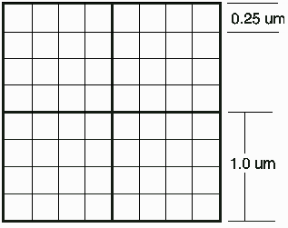
Consider the case where the designer sets up a pixel size of 1x1 um and the machine’s grid address is 0.25 um. In this case it is simply not possible to get 256 levels of grey.
First of all, it is not possible to easily vary the spot size in the center of the dot because pixels are snapped to grid. Secondly, one can only get 16 distinct levels of grey and the various dots will not be symmetric.


There are many ways to arrange the pixels within a dot to get the desired density - shown at left is one possible arrangement.
A lookup table can be built for the program that contains the pixel placement for each level of gray. This gives the mask designer more control should it be needed.
IC imaging devices are capable of handling extremely large file sizes - so for a 1024 x 1024 image it is generally not critical to do much compression or optimization.
If the bitmap becomes quite large and has many levels of grey, the file size can get large and the processing time (the conversion from GDSII to MEBEs for example) can also rise to the point where the mask cost will increase to reflect that.
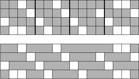
One way to reduce the GDSII file size is to combine the individual pixels into larger rectangles when they are adjacent. This can signficantly reduce the number of “rectangles” in the GDSII file and speeds up the GDSII to MEBES fracturing.

Top: Before Compression. Four adjacent pixels as created from the greyscale levels. There are 47 digitized rectangles in the top file.
Bottom: After Compression. Combining adjacent sub pixels results in 17 digitized rectangles. Since MEBES is restricted to trapezoids, a simple row compression is relatively good. GDSII could benefit from both row and column merging.
Should extremely large bitmaps that generate GDSII files in excess of 2GB be envisioned, we would recommend that rather than go to GDSII the program be modified to directly output MEBES.
Artwork Conversion has been writing GDSII readers and writers since 1989 and has over 5000 licenses of our GDSII conversion tools in use. We can quickly take your requirements for converting bitmaps into GDSII (or even into MEBES) and produce a program that will quickly and effectively produce the mask data you need.
Our expertise extends into additional operations such as compression, viewing and plotting large data sets. We can offer code both on Windows and UNIX platforms.
Finally, if you are still in the early experimental stage we offer such conversions as a service.