SolidWorks Web Page Header

GBR2DXF Experiment

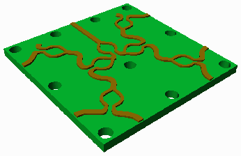
microwave circuit drawn in SolidWorks

We will convert the Gerber files into DXF using Artwork's GBR2DXF low cost translator. Traces will be mapped to polylines with width, round pads to circles, outlines to zero width closed polylines.

Conversion Parameters

    Traces - set to connectivity. This means that the converter does not draw small donuts at each end to simulate the half round of the trace.

    Draws/Flashes - set to solid which means that traces are drawn using polylines with width.

    Block Flashes - exploded. This means that each flash that would normally be a "block" in AutoCAD is instead exploded.

    Circles Control - circles - means that round pads are drawn as circles and not as donuts.


What The DXF Looks Like
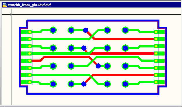
DXF from Gerber to DXF

The circuit traces are polylines with width. The rectangular and square pads are "solids" and the round pads are "dounuts" AutoCAD donuts are actually two polyline arcs with width. dxf_from_gbr2dxf_solid.zip

Importing into SolidWorks

So, let's import this into SolidWorks and see what we get. What would we like to get? Something like a multi-layer sandwidth: Each Gerber conductor layer on its own Z-level in SolidWorks with a given thickness. Between each conductor layer a solid body representing the FR4. Drill holes running through the entire assembly like toothpicks holding the whole thing together.

Importing

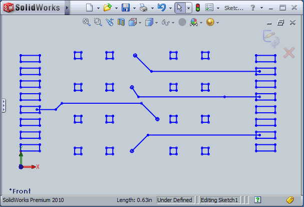
We are going to import into a SolidWorks part. We will start by just importing the top layer. We import it as a new part and the data as a 2D Sketch. here is what it looks like as it first comes in:

DXF imported into 2D sketch

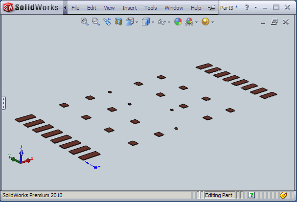
You can see that our circuit traces have lost their width but the solids for the square pads are OK. To convert this to a part, we have to selected the closed regions (i.e. the pads) and extrude them along Z. The actual thickness is about 0.0014 inch (assuming 1 oz.copper) but we will use 0.004 inch so that we can actually see something in 3D.

In order to extrude this, I had to first delete the sketch lines for the traces (as they don't form a closed body they can't be there), select the rest of the 2D sketch lines and then use the extude/boss function to extrude by 0.004 inch in the Z direction. I also set the material to copper which gives the data its brownish color.

DXF imported into 2D sketch

I can now save this as a "part" we'll call TOP_LAYER.SLDPRT

So you can see that to import just one layer requires several manual steps and we have yet to be able to import the traces.