 |
Spiral Rasterizer for DVD Disc MasterSteve DiBartolomeo 
Glass mastering systems are currently used to create CDs, DVDs, HD-DVDs and Blueray masters. Owners of such machines would like to adapt the mastering equipment for use in making micro electronic and optical structures with critical dimensions down to a micron. In this dimension range, these disc mastering machines could be much more cost effective than using an E-Beam system to write a similar sized mask. Most micro electronic structures are described using the GDSII data format. This format has been in use since the early 1980’s and consists primarily of boundary and paths which are organized both by layer and by a hierarchy of repeated cells. |
|
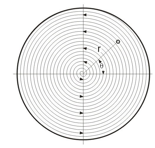
The CD/DVD mastering system uses a completely different approach when writing the data than a conventional E-beam or laser pattern generator. The laser spot follows a spiral pattern, starting near the center of the disk and working out towards the periphery of the disk. The consequence is (at least from a data prep point-of-view) that the bitmap used to drive the laser must be ordered in a radial fashion. . |

|
Magnitude of the ProblemSo how difficult is it to convert the industry standard GDSII layout data into a "radial" bitmap? Let's delve into this and come up with an answer. |
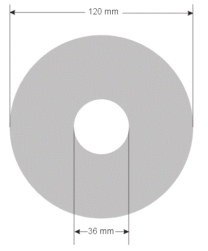
Radial ParametersIn order to understand what is required of the radial RIP, let's do some back-of-the-envelope computations to estimate the number of pixels, lines and data size. We will assume an image area bounded by an inner diameter of 36 mm and an outer diameter of 120 mm. I will try to compute everything in a way that makes it straightforward to change both diameters. |

|
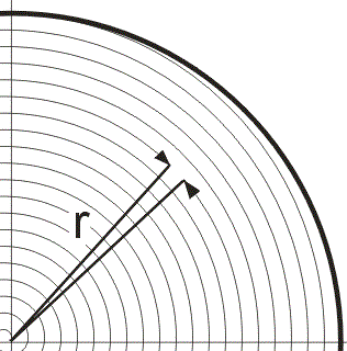
Track PitchThe distance (measured along the radius) between each complete revolution. Also known as track width or radial pitch when converted to a DPI value. A typical pitch is 0.1 um but can be varied by the equipment. |
|
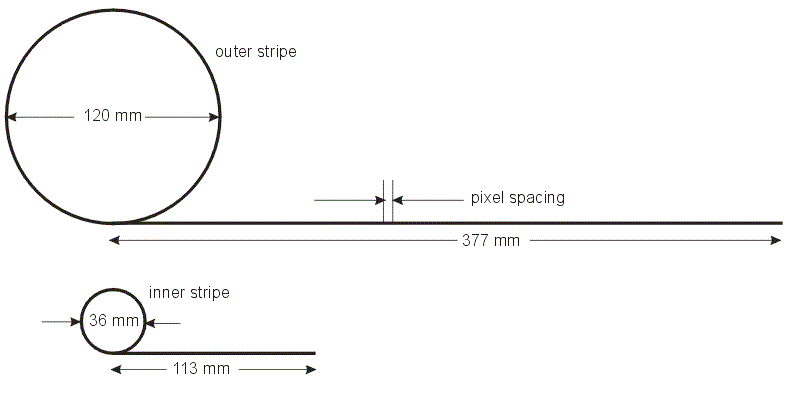
Tangential ResolutionThe distance measured tangentially to the radius between data points (i.e. between the centers of two pixels.) How this pitch is defined and used depends on the recording method. There are two methods: CAV - constant angular velocity CLV - constant linear velocity I am told that CAV is the default writing mode for these mastering machines so that is what we will use for our computations. For CAV, physical pixel spacing is determined by setting a specific pixel (pulse) frequency and a fixed rotation speed of the disc during mastering. |

|
Unraveling the DiscIf we "unravel" the inner cylinder and the outer cylinder we have two different length strips that are exposed in the same amount of time (i.e. the time to make one revolution.) That means for the outer strip, the pixels will be spaced farther apart since the laser pulse frequency is constant and the time for one rotation is constant. 
|
Next - How Many Pixels |