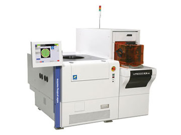
Tokyo Seimitsu/Accretch UF3000 Wafer Map Format
|
Source Documentation Information sourced from: A-PM-90A / UF Series |
 |
This binary file format follows the A-PM-90A / UF series of probers from Tokyo Seimitsu Co. Ltd.
The binary file is divided into three sections: a header, test results per die and Line Category per die. There seems to be alternative architectures characterized as: normal, 250,000 chip and 256 Multi.
The fields that are of interest to us when extracting header data from this binary file are:
Device Name:                  alphanumeric
Wafer Size:                   a list of available sizes (in inches and mm)
Index Size X                  in units of 0.01 um
Index Size Y                  in units of 0.01 um
Flat Orientation              (in degrees)
Map Version:                  0,1,2,3,4
Map row size:                 number of die positions in X
Map line size:                number of die positions in Y
Wafer ID:                     alphanumeric
X coord positive direction    left | right
Y coord positive direction    up   | down
Type of Reference Die:        Wafer Center Die, Target Sense Die, Teaching Die
Target Die X                  (measured from wafer center in units of 0.01 um)
Target Die Y                  (measured from wafer center in units of 0.01 um)
Reference Die Index (X)       x postion
Reference Die Index (Y)       y position
Probing Start Position        (UL, LL, UR, LR)
Probing Direction:

Test Die Data Address Offset: (Hex)
The results by die is stored as an array of groups of 6 bytes (3 words) starting at the offset address. Encoded into these words are X and Y index position of the die and category data.
UF3000 Data Dump Utility
During development of the UF3000 binary parser, it was helpful to output every defined field to a simple ASCII readout. We could then attempt to interpret the meaning of the field as the documentation was extremely terse and translated from Japanese. Our users can access this dump function from the command line engine as detailed here.
Dumping Data from a UF 3000 Binary Map File
The wmapconverteng.exe engine can be used to make a complete "dump" of the UF 3000 Binary map file format. This ASCII output can be useful for examining the contents of the binary file.
Syntax
wmapconverteng.exe
     input_file_name
          output_file_name
               -dir:directory
                    -inputformat:UF3000
                         -uf3000_info

where:

wmapconverteng.exe      wafer map convert engine exectuable
input_file_name         name of the Binary UF 3000 file to process
output_file_name        base name for output text file
-dir:directory          directory where the output file should go
-inputformat:UF3000     identifies the file as a UF3000 binary file
-uf3000_info            directive to produce an ascii data dump
Sample ASCII
I've obfuscated some of the proprietary data in this file
P46X71-21B7
This is a 164KB UF 3000 binary file as our input. It produces a 13.3 MByte ASCII file.
UF Binary Header Information:

Wafer Testing Setup Data
  Operator Name: AAAA
  Device Name: 000A081A0AA-AA0
  Wafer Size: 300
  Machine No.: 0
  Index Size X: 195680                         <- pitch
  Index Size Y: 272960                         <- pitch
  Standard Orientation Flat Direction: 180
  Final Editing Machine type: 0

Map Version:2 (256 Multi-sites)

Map data area row size:152                     <- array size
Map data area col size:110                     <- array size

Map Data Form:0 (6 bytes)                      <- 6 bytes (3 words) per die

Wafer Specific Data
  Wafer ID: A00A00-21B7
  Number of Probing: 0                         <- this should not be 0
  Lot No.: A00A00.0A
  Cassette No.: 1
  Slot No.: 2

Wafer Probing Coord System Data
  X coordinates increase direction: 1 (leftward)
  Y coordinates increase direction: 1 (forward)
  Reference die setting procedures: 3 (Target sense die)
  (Reserved): 0x00
  Target die position X: 0 (Unit: 0.01um)
  Target die position Y: 0 (Unit: 0.01um)
  Reference die coordinator X: 10
  Reference die coordinator Y: 35
  Probing start position: 2 (upper-right)
  Probing direction: 1 (leftward)
  (Reserved): 0x0000
  Distance X to wafer center die origin: 0 (Unit: um)
  Distance Y to wafer center die origin: 0 (Unit: um)
  Coordinator X of wafer center die: 77
  Coordinator Y of wafer center die: 56
Index File
An index file (.idx) of map data is not used or considered. We are only working directly with the MAP file itself. The documentation indicates that map file names take the form: MAP_NNNN.DAT but we have not found this to be the case when clients send us map files.
Reference Device
Probers must identify and use a known reference device in order to test a wafer. The UF3000 MAP file appears to allow a number of different ways to define a reference device.
Let's examine these options and look at data we've received from sample files.