AIF II Extension for Multiple Die
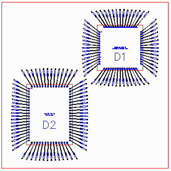
Several users of AIF have asked Artwork to support multiple die on a single substrate. While the AIF II specification supports in principal only a single die and single substrate we have attempted here to "extend" AIF II to help describe MCM's and stacked die.

New MCM Keyword in the DATABASE Section
The first step is to add a keyword in the database section that tells the AIF parser that there will be extra items in the AIF II file to describe more than one die.
[DATABASE]
TYPE=AIF
VERSION=2.0
UNITS=UM
MCM=TRUE
The line, MCM=TRUE, tells the parser that there will be multiple DIE definitions.
New Section [MCM_DIE]
A new section is added called [MCM_DIE] which lists the die "packages" and also the reference designator associated with that die package.
[MCM_DIE]
2P528A_A0=D1
COTULLA_C0=D2, D3
This section will have one line per die definition. In the text above, there is a die definition called 2P528A_A0 which is inserted with reference designator D1 and there is a second die definition called COTULLA_C0 which is inserted twice - once as D2 and once as D3. Please note that each reference designator should be unique even if the same die is placed twice.
Describing each MCM Die
Each MCM die placement is described in its own section. The description is limited to the die outline and center location and an optional thickness parameter.
[MCM_2P528A_A0_D1]
WIDTH=7.2924
HEIGHT=7.2314
CENTER=0.000, 0.000
The section name begins with "MCM" and then is concatenated with the die package definition name (using the underbar _ as a link to avoid spaces) followed by the reference designator.
The next line is the width of the die outline (along X)
The next line is the height of the die outline (along Y)
The next line is the center of the die outline
These three lines allow a reader to draw this die insertion's outline.
Netlist Section
The basic syntax of the netlist section does not change. However each die pad number (or name) now must the reference designator along with the pin number.
[NETLIST]
SIG-1   D1.1  DP80 -5.000 5.000 A3   RND700 -11.000 13.000 2 BF -6.342 7.011 44.3
In the above example, the die pad number (Column 2) is D1.1 which means die pad #1 on ref designator D1. The coordinates of the pin D1.1 are absolute -- not relative to the center of D1 so there is no translation needed to directly draw the pin but there would be a coordinate translation needed if you are building a symbol for the package.
In the above example you can also see the ball assignment (which is optional, if no ball use dash's to hold the place) adn then the bond finger assignment. The bondfinger is independent of the die or BGA packages i.e. we don't associate a bond finger with a particular die insertion.
Die to Die Wire Connections
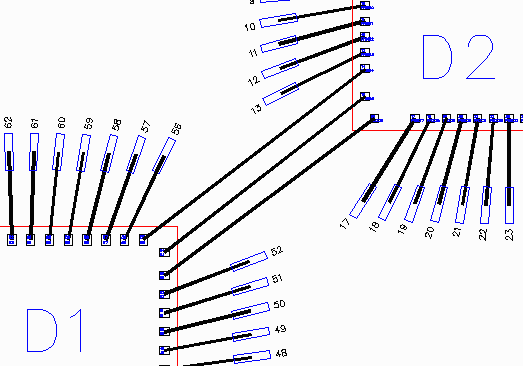
The [NETLIST] syntax has no way of defining a wire from a die pad to a die pad on a different die. Since we did not want to break the backward compatibility of the AIF II format we took an approach that means some additional work for the parser.

The second die pad is located where normally the ballpad information would be. The parser has to be able to distinguish between a ball pad and a die pad based on the pad's name - a ball pad will always have a JEDEC label such as A15, AB24 but the die pad will have a reference designator followed by the pin number such as D2.32.
SIGA  D1.53 DP80X60  XXXX YYYYY  D2.16  DP75  XXXX  YYYYY  -  -  -  -  -
SIGB  D1.54 DP80X60  XXXX YYYYY  D2.15  DP75  XXXX  YYYYY  -  -  -  -  -
SIGC  D1.55 DP80X60  XXXX YYYYY  D2.14  DP75  XXXX  YYYYY  -  -  -  -  -