

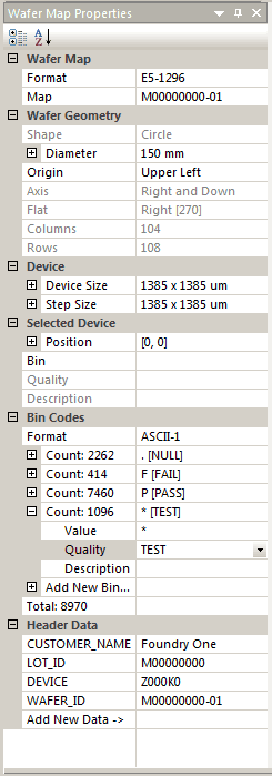
This chapter defines WMEdit's Wafer Map Properties Window and dialogs. This window displays the Map File's properties; some of the properties can be edited or filled in if the wafer map is missing properties or if you need to change properties (such as bin codes) in the process of converting to a different map format.
Format - the format of the opened map file. To convert to a different map file, use the drop down and select from the list of available files.
Map - the "name" of the map file. Some map formats may have a number of maps in them. In this case, use the drop down to select the desired map within the file.
Wafer GeometryShape - currently only a Circle shape is supported.
Diameter - wafer size (and units). Normally read from the input map file, but if not present the user can enter the correct value. Size units can be different than the die size units.
Origin - Map files normally have an origin location for the matrix.
Axis - Map files have axis information as to the direction of increasing X and increasing Y values for the array.
Flat - a flat or notch is present on every wafer and the location is shown here. This is not editable but can be modified by rotating the entire wafer.
Columns - the number of columns in the array of devices. May include "empty" (or NULL) columns.
Rows - the number of rows in the array of devices. May include empty (or NULL) rows.
Device
Device Size - the X and Y dimensions of the device. The user can also specify the units. Some wafer maps do not provide the device size. The user can enter the values here or in the Step Size section.
Step Size - the step pitch (center to center) along X and Y. Virtually all map files assume the device size and the pitch are the same value.
Bin Codes
This section provides information on the bin codes present in the map file and also enables the user to modify bin code properties and to create new bin codes if needed as part of the editing process.
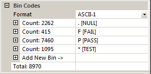
Format - displays the current Bin Code format: ASCII-1, HEXADECIMAL-2 and INTEGER-3 are the most commonly used formats for bin codes. All of these support up to 256 unique bin codes. If you need to change the bin code format (for example, when converting from a format that uses HEX-2 to ASCII-1) then use the drop down and select the appropriate bin code format for your new map format.
Modifying Bin Codes - The user can modify the bin code and it's attributes. Click on the plus sign next to the bin code row and you will see the value, quality attribute and a user defined description.

To change the bin code to a new value type it in. In the figure below I have changed the value from * to S.
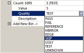
To change the Quality use the drop down to select from one of the available qualities. In the figure above I am changing the bin code quality to SKIP. To change or add a description, type it in. [Note: only a few map formats support a free-form description]
Adding a New Bin Code - To creat a new bin code use open the section and type in a new code (not one that already is in use) You can also select the Quality from the drop down list. Once you have created a new bin code, you are then able to select one or more die and change their existing bin codes to the new one.
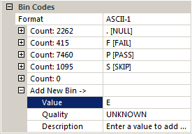
In the figure above, we added a new bin code "E" and we will assign it a Quality "EDGE" using the drop down.
Selected Device
When the user "selects" a particular device in the matrix, the properties of that device will appear in this section. The user can modify those properties (i.e. this is where the Editing function is implemented in WMEdit.)
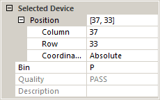
Position - editing the position values will move the devices that is selected to the new position as will editing the column or row values.
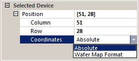
Coordinates - by default, WMEdit displays the array coordinates of the devices with the origin in the Upper Left of the array beginning at 0,0. Increasing X is to the right and increasing Y is down. Some map formats use a different coordinate system which can be displayed by using the pulldown to change Absolute to Map.
Bin - Selecting a different bin (use the drop down list) will change the bin assignment of the selected device.
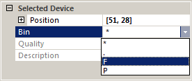
If you want to change the selected device to a new bin, you must first create that bin in the Bin Codes section.
Back to the Table of Contents