Holes and Islands
One of our primary customers for this product is having some difficulties with the use of re-entrant polygons in the output and would like Artwork to provide a different output geometry.
What is the Problem
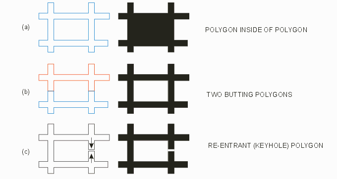
A hole is a region completely surrounded by "metal" (where we assume metal is represented by the digitized data.) For example, if four paths cross as shown below they can be considered to form a polygon with a hole inside of it.

How To Represent a Hole In Gerber?
One has choices in representing the hole in the Gerber database. First, we are using the G36/G37 polyfill command. Any closed polygon boundary is filled. Further, it is either bad practice or forbidden to create self intersecting polygons. Finally, there is no such entity in RS274X as a "clear" or "negative" polygon. Given those guidelines what are our choices?

Case (a)
Simply putting the polygon representing the "hole" inside the outer polygon does not work as RS247X does not recognize an empty or clear polygon. The resulting mask is not what was intended.
Case (b)
We can produce the "hole" by surrounding it with two (or more) polygons that "butt up to each other" We call this the "butting" option and it generally works fine.
Case (c)
We can produce the "hole" by following what is known as a keyhole path - essentially we wind into the hole in one direction and back out in the other direction. The gap in the illustration is not really there - it is only shown so that you can see where the cut line occurs. This approach is commonly used in the IC layout industry - however some rasterizing algorithms have difficulty with the keyhole approach and may fail or crash if such a polygon is encountered.
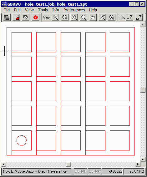
As of version 1.10 Case (c) is the output choice used by OASIS2GBR as you can see in the test case below:
Running a Simple Example
In order to make some tests I created a simple GDSII file and ran it through oasis2gbr. The command line used is shown below:
c:\wcad\GerberExtract64\gbrxtrakapp64.exe hole_test.gds hole_test1.gbr
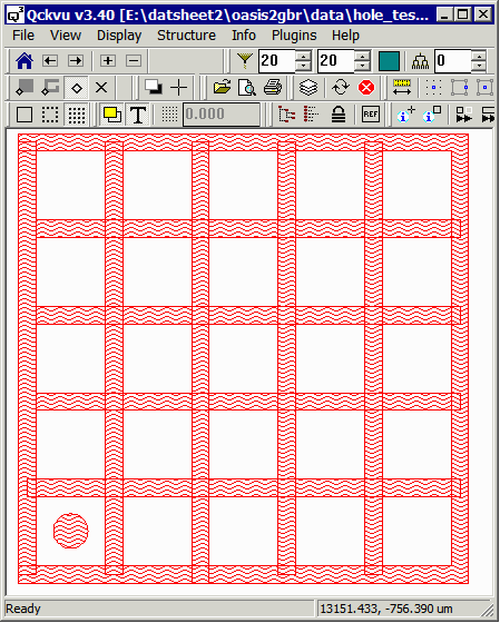
The input file is a simple GDSII consisting of a number of paths that intersect to form a hatched region and a single round pad inside one of the islands formed by the paths.

The output Gerber file consists of a large re-entrant (keyhole) polygon (with many cut line paths) and a round polygon for the pad. The outer polygon has 115 vertices.

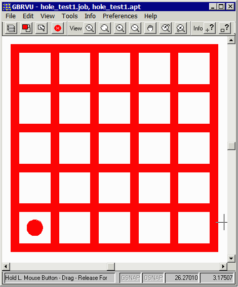
When rasterized by a photoplotter that supports G36/G37 polyfill the final results will look like:

The Customer's Problem?
Our user has reported that this approach is not working well. Why? Apparently there is a one pixel uncertainty when placing each polygon vertex. Under some conditions, the vertices of the cut line in and the cut line out are snapped to different pixels leaving a gap in the mask. The next page will describe this and some options for addressing it.
