
This page contains a number of examples that show how the annotation directives operate. We will use a small and simple panel with 6 circuits.

Figure 1 - the test panel for our annotation examples: test_panel.gds.
Layer 1 - metal layer (black)
Layer 2 - reserved areas for text annotation (green)
Layer 3 - text coordinates for insertion (blue)
Layer 63 - construction lines (cyan)
If one zooms in on the lower left of the panel you can see in more detail the insertion coordinates we will use to place out text annotations.
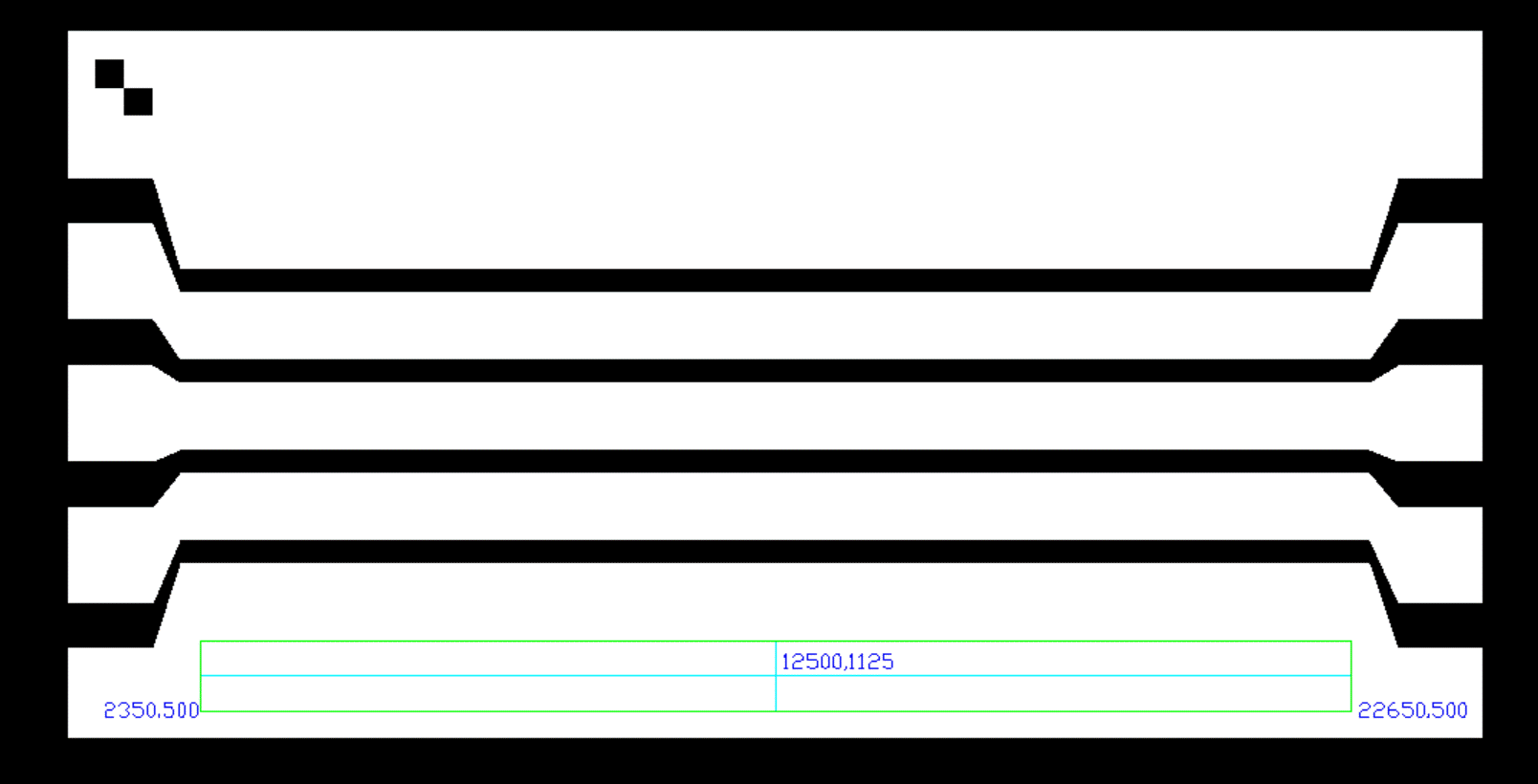
Figure 2 - zoomed into the lower left circuit of the test panel.
SFGEN SETTINGS
For each example, we always use the same SFGEN settings. We process layer 1 for output (the other layers were created primarily to help us compute the insertion points for the annotation text).
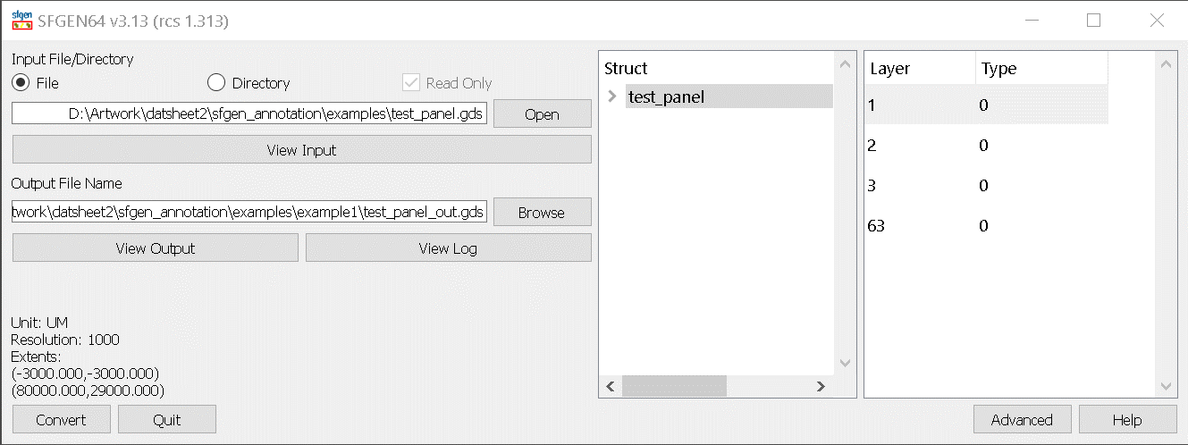
Figure 3 - SFGEN Main Dialog showing test_panel.gds loaded and layer 1 selected.
We then use the Advanced Settings tab labeled annotations to point to the desired insertion file.
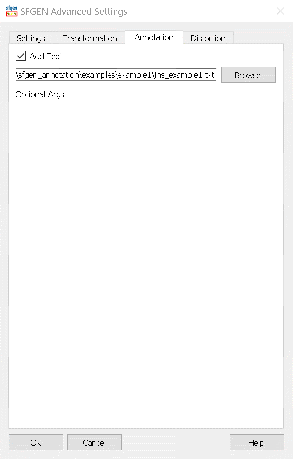
Figure 4 - Advanced Annotations Tab with path to annotations insertion file defined.
The insertion file has two main sections: a GLOBAL (mandatory) section followed by one or more TEXT_ANNOTATION sections. For our examples, we will mostly keep the GLOBAL directives constant (unless specifically noted where we are exercising some of the global directives) and it is show below:
GLOBAL Section
B_GLOBAL

#

MODAL NO


# annotation file units: UM, MM,

# CM, INCH, MILS

# SGEN GDS output is always in UM

# UNITS UM


# ouput file precision

# optional - defaults to GDS

#input file grid

GRID 0.001


# stroked text weight

STROKE_WEIGHT 10


# text aspect ratio:

# > 1.0 -> wide,

# < 1.0 narrow

# text height constant

ASPECT 1


# text slant in degrees

SLANT 0


# multi line text spacing

#  X text height

SPACING 1.2


# read only font repository

TTF_FONTDIR C:\WCAD\SFGEN64\

EXAMPLES\Annotations\Fonts


# scratchpad area for compiled fonts

FONTDIR C:\Temp\fontscratchpad


# default folder for bitmaps

BITMAPDIR C:\WCAD\SFGEN64\

EXAMPLES\Annotations\Bitmaps\PN1


# bitmap pixel size in um

PIXELSIZE_UM 7
# circularize: smooth contour

# fillable fonts/text

CIRCULARIZE yes


# used when CIRCULARIZE=yes

ARCRES 45.0


# used when CIRCULARIZE=yes

ARCRECOVERY 0.5 0.1


# unionize bitmap images

UNIONIZE yes


# union output: butting or cutline

UNION_FLAVOR cutline


# max num of thread to spawn

THREADS 4


# log detail level

LOG_LEVEL 1


# threshold count between

# binary and linear searches

#  associated with finding

# duplicate bitmap and text strings

SORT_SIZE 500000


# controls GDS output of annotations:

# flat or hierarchy

# OUTPUT_CLASS flat

OUTPUT_CLASS hierarchy


E_GLOBAL
We are going to insert a text annotation in the lower left circuit. Based on our layout, the text will be left (bottom) justified, it will be inserted at coordinates 2350,500 and we will set it to 1250 um high. The string is 800-555-2000-004 and we will use the font called bcssemi.ttf.
Here is the text annotation section which follows the global section:
B_TEXT_ANNOTATION

HEIGHT 1250

FONT bcssemi.ttf

XY 2350 500

B_STRING

800-555-2000-004

E_STRING

E_TEXT_ANNOTATION
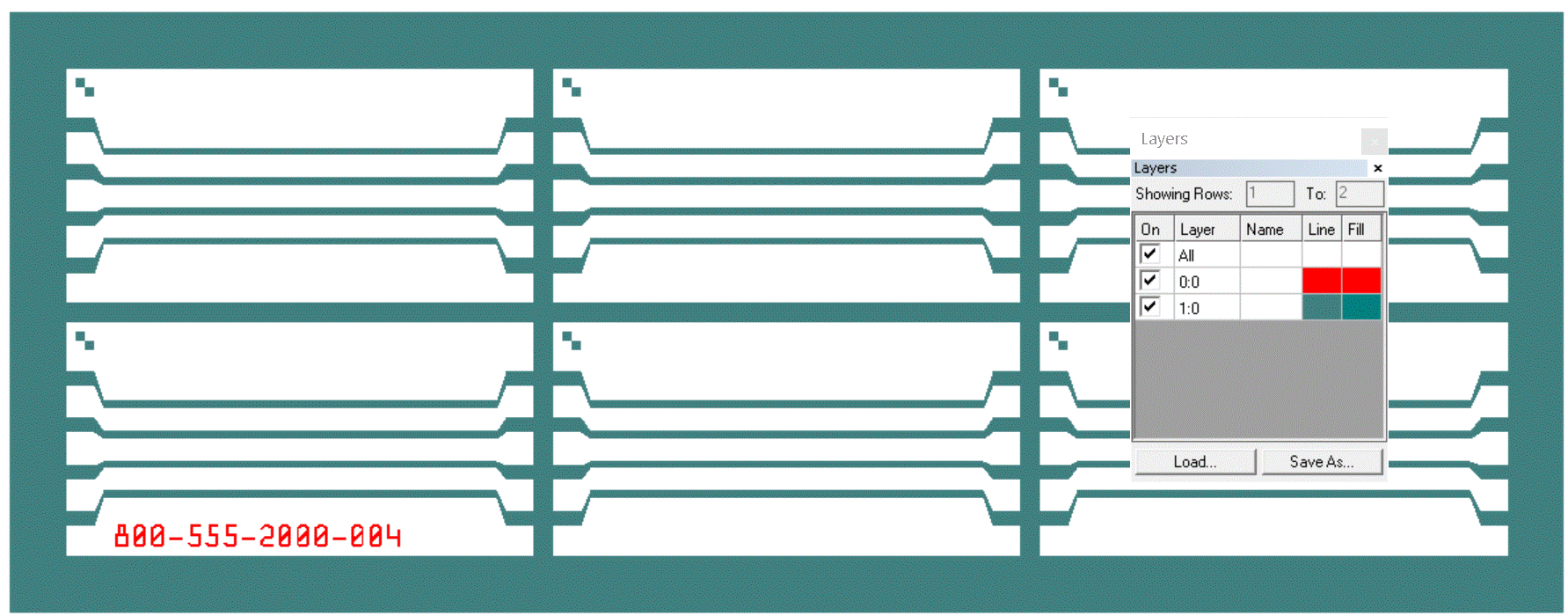
Figure 5 - Results of example 1 - annotation placed in lower left circuit
Notes:
1. The annotation polygons were placed on layer 0 - not layer 1. (this is default behavior)
2. The annotation polygons were generated into a cell and the cell was inserted. (due to the OUTPUT_CLASS=hierarchy)
If you need to place a text annotation where there is already digitized data, you can use the inverse directive to "cut" away the text. Let's see how that works. We are going to place a string, "800-555-2000" at coordinate 55500,-2500 with height = 2000 at the lower right of the panel. There is already digitized data there.
B_TEXT_ANNOTATION

HEIGHT 2000

FONT bcssemi.ttf

INVERSE on

XY 55500 -2500

B_STRING

800-555-2000

E_STRING

E_TEXT_ANNOTATION
B_TEXT_ANNOTATION

HEIGHT 1600

FONT bcssemi.ttf

INVERSE on

MARGIN 200

XY 55500 -2500

B_STRING

800-555-2000

E_STRING

E_TEXT_ANNOTATION

Figure 6 - Left: text height = 2000. Right: text height = 1600 and MARGIN = 200.
Notes:
1. I ran this twice - first with the text height=2000 but it looked ugly (left)
2. The second run (right) I reduced the text height to 1600 and added a 200 um margin. This looks better.
3. While our viewer seems to imply that the metal on Layer 1 was removed to generate the annotation, it was not. Instead, polygons were generated on layer 0 that must be "scratched" away by the rasterizer. This is a bit of a cheat but since our target is rasterization (and the rasterizer can easily do the scratch) this is an efficient approach. However there is a big limitation to this approach: if you have multiple text annotations, you cannot have both positive and inverse annotations at the same time!
The default insertion point for a text annotation is the bottom left corner of the box that surrounds the text. However the user is not limited to this reference point and there are situations when a different juctifcation is desireable.

Figure 7 - Text justification locations
Let's look at some examples where we combine a MIDDLE-MIDDLE justification with rotation and miroring. First, we are going to demonstrate the effect of changing the vertical justification:
# Example 3a:

# MIDDLE-BOTTOM Justification

# No Rotation/Mirroring

B_TEXT_ANNOTATION

HEIGHT 1250

FONT bcssemi.ttf

HJUST MIDDLE

VJUST BOTTOM

# ROTATION 0

# MIRRORX  0

# MIRRORY  0

XY 12500 1125

B_STRING

800-555-2000-004

E_STRING

E_TEXT_ANNOTATION
# Example 3a:

# MIDDLE-MIDDLE Justification

# No Rotation/Mirroring

B_TEXT_ANNOTATION

HEIGHT 1250

FONT bcssemi.ttf

HJUST MIDDLE

VJUST MIDDLE

# ROTATION 0

# MIRRORX  0

# MIRRORY  0

XY 38500 1125

B_STRING

800-555-2000-004

E_STRING

E_TEXT_ANNOTATION
# Example 3a:

# MIDDLE-TOP Justification

# No Rotation/Mirroring

B_TEXT_ANNOTATION

HEIGHT 1250

FONT bcssemi.ttf

HJUST MIDDLE

VJUST TOP

# ROTATION 0

# MIRRORX  0

# MIRRORY  0

XY 64500 1125

B_STRING

800-555-2000-004

E_STRING

E_TEXT_ANNOTATION
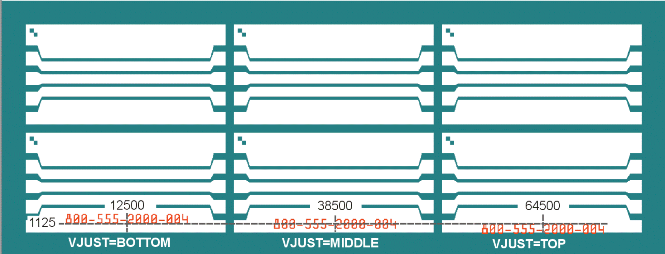
Figure 8 - Text annotation position for VJUST = BOTTOM, MIDDLE, TOP
Now we are going to return the VJUST back to MIDDLE for all three circuits and apply rotation of 90, 180 and 270.
# Example 3b:

#MIDDLE-MIDDLE Justification

# Rotation = 90

B_TEXT_ANNOTATION

HEIGHT 1250

FONT bcssemi.ttf

HJUST MIDDLE

VJUST MIDDLE

ROTATION 90

# MIRRORX  0

# MIRRORY  0

XY 12500 1125

B_STRING

800-555-2000-004

E_STRING

E_TEXT_ANNOTATION
# Example 3b:

# MIDDLE-MIDDLE Justification

# Rotation = 180

B_TEXT_ANNOTATION

HEIGHT 1250

FONT bcssemi.ttf

HJUST MIDDLE

VJUST MIDDLE

ROTATION 180

# MIRRORX  0

# MIRRORY  0

XY 38500 1125

B_STRING

800-555-2000-004

E_STRING

E_TEXT_ANNOTATION
# Example 3b:

# MIDDLE-MIDDLE Justification

# Rotation = 270

B_TEXT_ANNOTATION

HEIGHT 1250

FONT bcssemi.ttf

HJUST MIDDLE

VJUST MIDDLE

ROTATION 270

# MIRRORX  0

# MIRRORY  0

XY 64500 1125

B_STRING

800-555-2000-004

E_STRING

E_TEXT_ANNOTATION
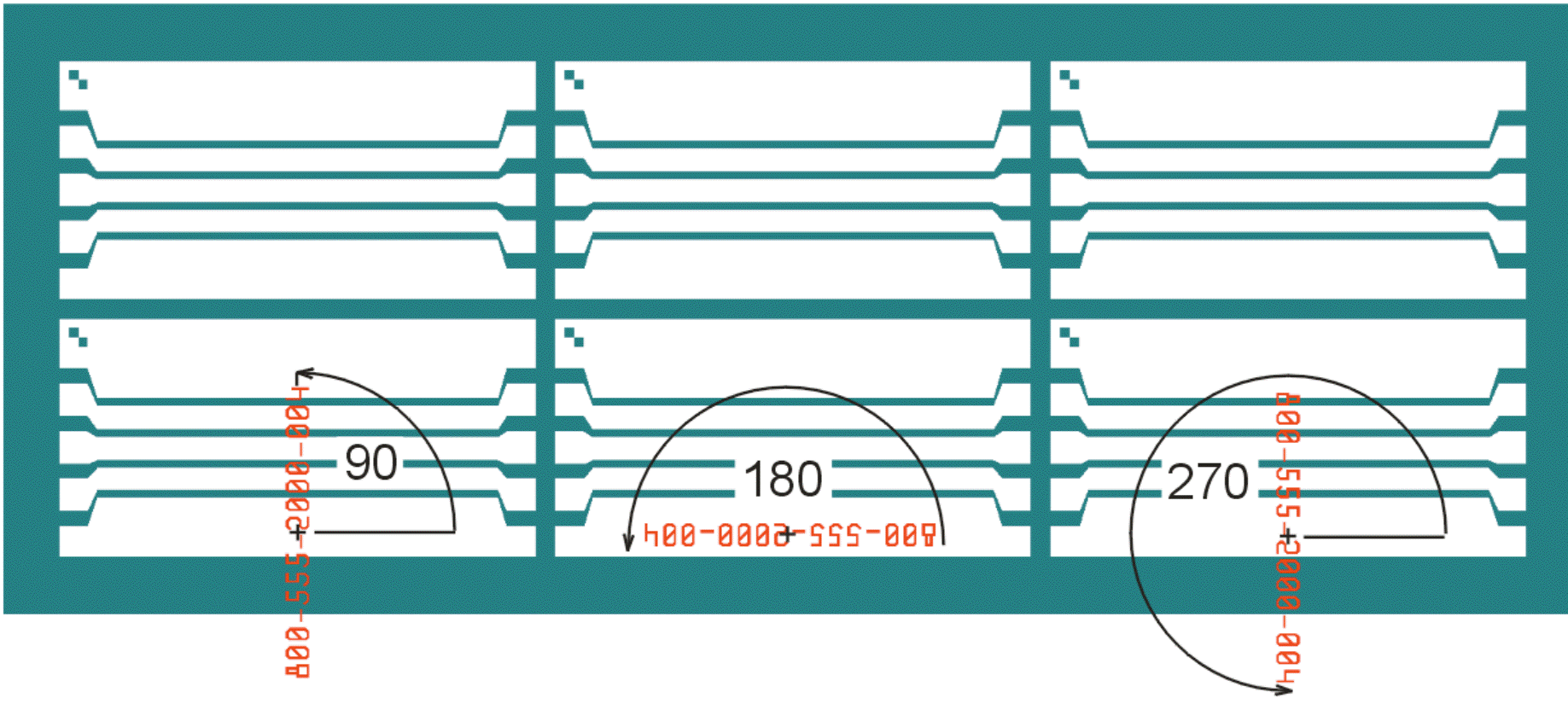
Figure 9 - Since the insertion point is at the center of the text bounding box, the rotation also proceeds around that point.
Let's see how mirroring along X and Y work with the MIDDLE-MIDDLE text insertion.
# Example 3c:

#MIDDLE-MIDDLE Justification

# MirrorX

B_TEXT_ANNOTATION

HEIGHT 1250

FONT bcssemi.ttf

HJUST MIDDLE

VJUST MIDDLE

ROTATION 0

MIRRORX  0

# MIRRORY  0

XY 12500 1125

B_STRING

800-555-2000-004

E_STRING

E_TEXT_ANNOTATION
# Example 3c:

# MIDDLE-MIDDLE Justification

# MirrorY

B_TEXT_ANNOTATION

HEIGHT 1250

FONT bcssemi.ttf

HJUST MIDDLE

VJUST MIDDLE

ROTATION 0

# MIRRORX  0

MIRRORY  0

XY 38500 1125

B_STRING

800-555-2000-004

E_STRING

E_TEXT_ANNOTATION
# Example 3c:

# MIDDLE-MIDDLE Justification

# Mirror X and Y

B_TEXT_ANNOTATION

HEIGHT 1250

FONT bcssemi.ttf

HJUST MIDDLE

VJUST MIDDLE

ROTATION 0

MIRRORX  0

MIRRORY  0

XY 64500 1125

B_STRING

800-555-2000-004

E_STRING

E_TEXT_ANNOTATION
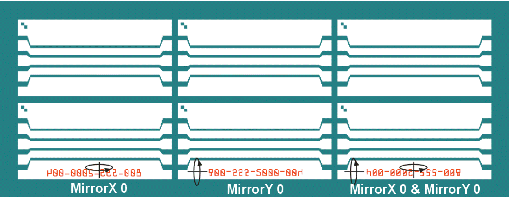
Figure 10 - Since the insertion point is at the center of the text bounding box, one does not have to compute the mirror anchor points to keep the location from "flying" away.