
One of our clients was provided with a gray scale TIFF image and asked to produce a reticle that could be used to step and repeat the image across a substrate. This app note shows a way to accomplish that. (Note - there are many ways to create such a reticle. We used the tools that we are familiar with and happen to have on hand.)
The mask writer can write only black or white. Therefore our first step is to convert the gray scale image to monochrome using Photoshop.
The image provided is 255 by 255 pixels; each pixel = 25 um (even though Photoshop shows the DPI = 72 we can ignore that.) To produce a reasonable approximation I decided to convert it to a monochrome bitmap where each "sub pixel" is 5 um which should give me about 25 levels of gray. One could choose a smaller sub pixel and approximate more gray levels at the expense of larger file size.
Using Photoshop's Image | Mode | Bitmap dialog to convert from 256 gray to monochrome.
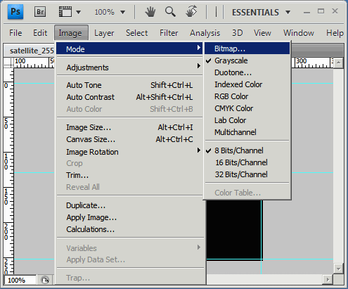
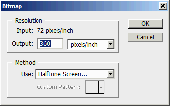
one has to choose the new DPI and a method to place the monochrome pixels. There are a number of methods which produce slightly different results. I decided to go with a halftone screen.
Notice that my Output resolution (360) is 5X the input resolution. This is what enables the monochrome image to approximate a gray scale image. To get more levels of gray use a higher multiplier such as 8 or 16.
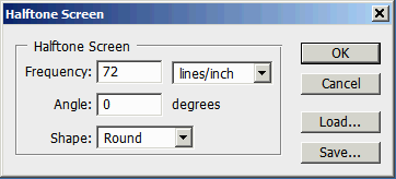
If you pick a Halftone screen then you must also pick the line frequency, screen dot shape and angle. These values are there for people who print with ink and who also have to deal with multiple colors.
Below you can see a portion of the image after conversion to monochrome with the halftone screen applied.
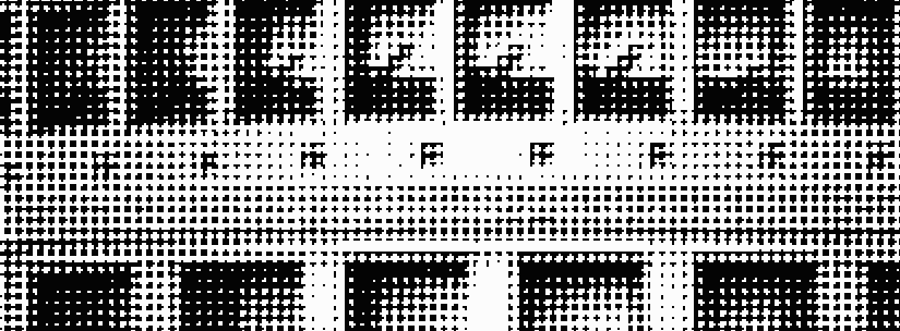
Other methods work including diffusion and pattern dither. The user can easily examine these in Photoshop and make a decision as to the trade off between file size and final image quality.
Since the mask writer wants a format such as GDSII we need to convert the bitmap. We use the tiff2mebes program (which can also produce GDSII instead of mebes.)
TIFF2MEBES is a command line program. Here is the command line used to create the conversion along with some notes as to what the various arguments control.
tiff2mebes.exe -pixel:5 -layer:1 satellite_pattern_halftone_round5x.tif sat_image.gds
where
| tiff2mebes.exe | name of the conversion program |
| -pixel:5 | 1 pixel = 5 um |
| -layer:1 | output layer = 1 |
| -gds | produce GDSII output |
| satellite_pattern_halftone_round5x.tif | input file |
| sat_image.gds | output file |
It takes less than 1 second for this program to run on a small file like this. Once the program is complete you have a GDSII file consisting of a large number of square and rectangular boundaries. Each black pixel in the input is "digitized."
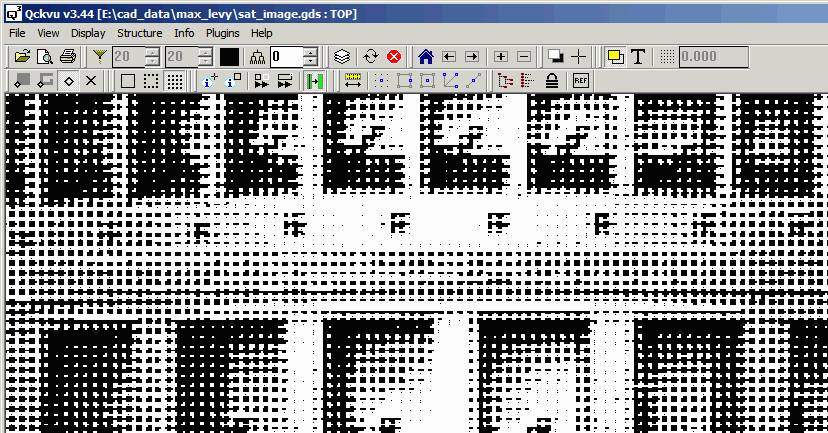
When creating a reticle one normally places the "product" several times across the reticle. The reticle background is normally "dark." I am calling this part of reticle the frame.
The frame can be drawn using a GDSII editor. In my case I have AutoCAD (and know how to use it) so I created the frame in AutoCAD and converted the DXF file into GDSII using ASM 3500.
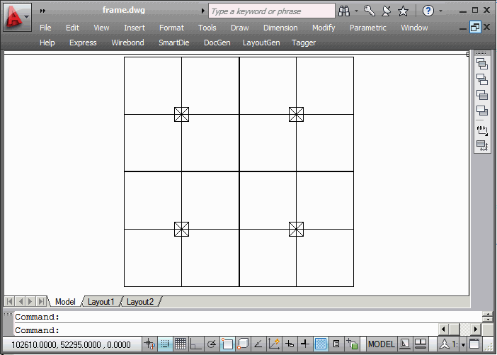
First I created a construction layer that defines the border, center and openings for the 4 satellite drop ins.
Then I drew a second layer using zero width closed polylines to define 8 boundaries that provide me the desired background and also leave a 10 um gap between quadrants and the correct sized opening. (The opening is computed by taking the 255 pixel image size x 25 um/pixel giving an opening of 6375 um.
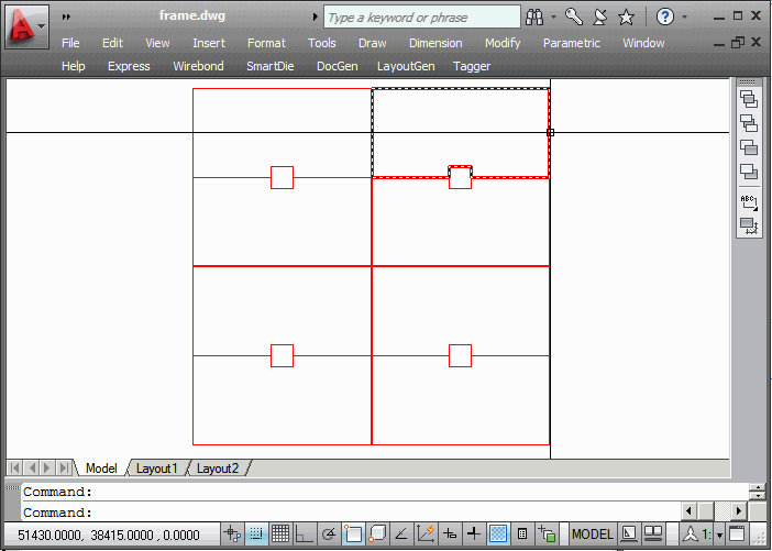
The overall size of the reticle is 102400 x 102400 um.
Now we need to convert our AutoCAD drawing of the frame into GDSII. I used Artwork's ASM 3500 (DXF to GDSII). There's not much to do here. Just make sure you tell the program that input and output are in UM with 0.001 resolution and that the layer called "opening" in AutoCAD gets mapped to layer 1 in GDSII.
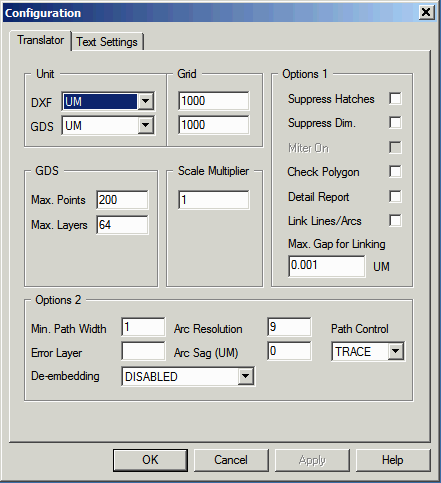
Configuration settings for dxf2gds.

Layer mapping from AutoCAD layer names to GDSI layer numbers.
At this point we have two GDSII files: frame.gds, the frame of the reticle and sat_image.gds, the satellite image which is our "product". We need to merge these two files into a single one so that the mask shop can produce the reticle.
The "product" file has to be placed 4 times -- once in each quadrant of the reticle.
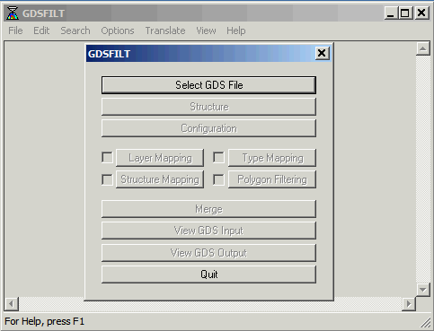
To do this we use Artwork's GDSFILT program - a utility that can be used to combine, merge, filter and flatten GDSII stream files.
We start up GDSFILT and load the frame.gds file.
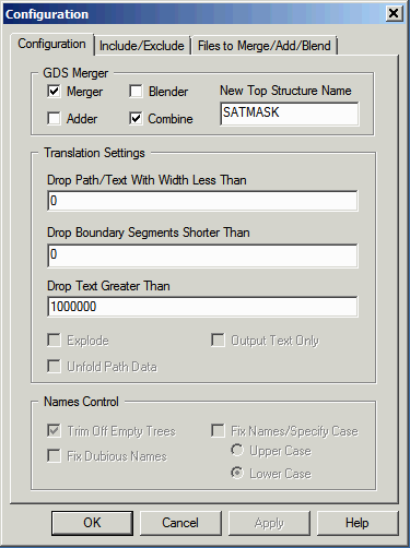
Now we go to the configuration section and check the boxes: MERGER and the box COMBINE. We define a unique top structure name since we don't want a "collision" with the existing top structure names in frame.gds or sat_image.gds.
Finally we go to the tab labeled: Files to Merge/Add/Blend and we select the sat_image.gds file and the structure TOP and enter the proper coordinates.
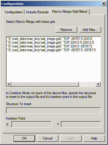
A note on coordinates ...
When the tiff2mebes program produces a GDSII file from the bitmap, it uses the lower left of the bitmap as the 0,0 point in the GDSII file instead of placing 0,0 at the center of the GDSII file. This means that when computing the insertion point one has to shift down and left by 1/2 of the size of the opening.
That's it. The resulting GDSII file can be sent to the mask shop to write the reticle.
Assuming you are familiar with the process and the tools:
| Planning | 5 minutes |
| Gray to Monochrome Conversion using Photoshop | 2 minutes |
| tiff2mebes conversion | 2 minutes |
| Drawing the reticle frame in AutoCAD | 15 minutes |
| DXF to GDSII conversion using ASM 3500 | 3 minutes |
| Merging the files with GDSFILT | 3 minutes |
| Reviewing and Measuring Results | 3 minutes |
| Total | 28 minutes |