
|
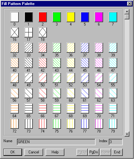
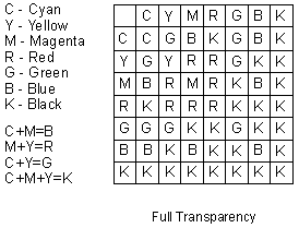
Fill Patterns for GDSPLOTThis file was generated by running the file colors.gds using the map file colors.map.  Selecting Layer Fill PatternsSelecting the proper fill patterns for clear plots is not always obvious. Most first time users select fill patterns that are much too dense and end up with a black plot. We offer the following general guidelines: metal layers - for scale factors on the order of 100-200 use a 25% fill with no outline such as 102 magenta and 103 cyan. By using these patterns you will be able to see layers under the metal. For higher scale factors such as 300-400 you can also use fill patters such as 54 (magenta) and 55 (cyan). nwell/pwell - usually no fill - just a dotted or dashed outline n+/p+ - no outline. Use a very light yellow such as pattern 100 contacts and vias - for scale factor 100-200 use solid black fill. For scale factors such as 300-400 you can use the special contact fill patterns 16,17,18 to differentiate between metal to metal, metal to active, and poly to active contacts and vias. active area - use a fill pattern such as 99-25% green glass - usually do not plot or just use an outline pad openings - usually just an outline or cross hatch in black using 89 polysilicon - often plotted in red - use 98 (25% red) Remember that all pixels imaged at a particular location are summed up to create the final color on that spot. A poor choice of fill patters will result in a very dark plot. How Colors InteractThe table below shows what color results when two colors overlap on the same pixel. 
If your company has developed custom fill patterns and colors for each process layer, GDSPLOT can match these closely. Differences may be due to the fact that inkjets run 300 dpi and most electrostatics sun 200 or 400 dpi. Our GDSPLOT software supports 300 DPI and most eletcrostatics run 200 to 400 dpi. Our GDSPLOT software supports up to 1024 custom fill patterns. Each fill pattern is defined as an array. Arrays can be 4x4, 8x8, and 32x32. When creating the array one ought to attempt to make sure that it is symmetrical in both X and Y so that it tiles cleanly. See the examples below of an “incorrect” fill pattern. Incorrect fill patterns will work but may appear jagged when plotted. Our GDSPLOT program reads the fill pattern definitions from a file called colfill.pat. The format of the ASCII file is as follows: The first index number must begin at 32 (0-31 are reserved for internal use) and can continue until 1024. We have a sample GDSII file with 256 layers defined that can be used to test your colfill.pat file called box256.gds. |