All About Calma's GDSII Stream Format [3]
Steve DiBartolomeo
Applications Manager
© 2011 Artwork Conversion Software, Inc.
GDSII BOUNDARY
The GDSII BOUNDARY record (geometric entity) is one of the two key geometries used to describe the layout (the other being the PATH)
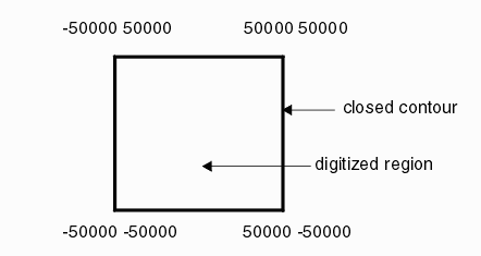
The boundary consists of a list of vertices which are connected by straight edges to form a closed contour. The "inside" of the contour is called the digitized area.
Number of Vertices per Boundary
The GDSII specification limits the number of vertices to 200.
This limit is totally arbitrary and was probably set at the time to limit the amount of computing power needed to render, store and process polygons. Most modern GDSII readers and writers support a much larger number such as 1024, 2048, or 4096. The actual upper limit is set by the design of the database. Since one of the records in the GDSII boundary defines the number of vertex pairs to follow, and that record is two bytes long the maximum number of coordinates would be 8191.
If you are developing a GDSII reader you should use the 8191 number as the maximum number of vertex pairs to ever expect. If you are writing a GDSII reader you should make the max number of vertices per polygon configurable so that the user can produce a GDSII file compatible with the target that is to read it.
Direction?
The direction of the vertices (i.e. clockwise or counterclockwise) has no meaning in GDSII and polygons can be written without concern as to their direction of their vertex order.
Self Touching
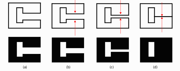
Self touching (also known as "re-entrant" or "keyhole") is not quite the same as self intersection and is actually allowed in GDSII. However it has to be done "correctly." Self touching is generally used to form islands or holes inside of a digitized region. The series of images below shows how a self touching, also known as re-entrant, boundary is created and how it will look on a mask when processed.

Polygon (a) is clearly legal as it does not self intersect or self-touch. Now imagine that the facing edges are slowly pushed towards each other (b) and (c) until they finally meet (d). Is (d) a legal polygon? Yes. It is not considered to be self intersecting but it does touch itself.
Multiple Holes
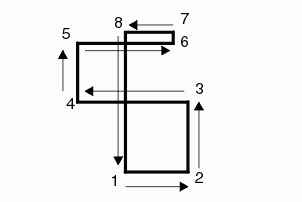
Multiple "holes" in a single boundary are common as shown below:

Interaction Between Boundaries
Each boundary stands alone and from a database point of view there is no interaction between boundaries. Other CAD systems may treat an "inner" boundary as a hole or cutout but this is not the case with GDSII.
Manhattan Data
Often one will hear the term "Manhattan." This means that all of the geometric data edges run vertical or horizontal. GDSII data need not be Manhattan but, mostly for computational reasons most digital IC layouts still used purely Manhattan data. Analog, high voltage and RF integrated circuits often use non-manhattan (also known as all-angle) layout.
Page
1 |
2 |
3 |
4 |
5 |
6


