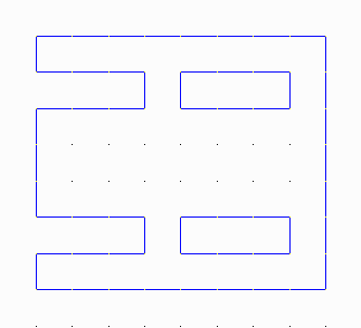
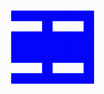
In AutoCAD you can define a solid hatch region which will appear as filled (shown before and after below).
|
In AutoCAD you can define a solid hatch region which will appear as filled (shown before and after below). |
|
 |
 |
|
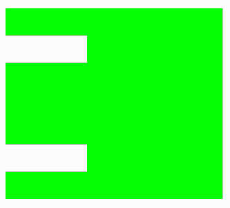
But, in reality the solid hatch is just a view option in AutoCAD and is NOT exported to DXF as an outline of a boundary and therefore will not get translated to Gerber. Below is an example of what the sample hatched DXF file will look like when translated to Gerber. The warning message next to it is what you can expect to see in the log file. |
 |
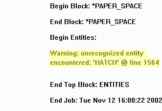 The warning message given in ASM 500. |
|
Here is the proper way to set up your drawing in AutoCAD to produce the proper "hatch-like" effect when translated to Gerber. This example uses two layers to demonstrate the proper technique, however the user my create as many layers as necessary, alternating from one to the other using a method we describe as "Paint and Scratch". |
||
|
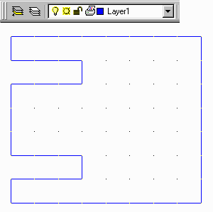
First create two seperate layers in AutoCAD. On the |
Next, change layers (shown at left), and draw the second set of polygons which need to be clear, (shown below). |
|
|

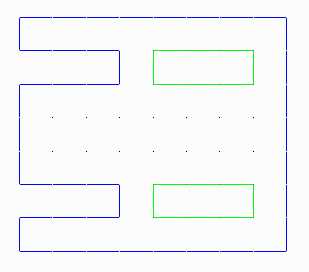
|
|
When finished, save the DXF file and close down AutoCAD. Start up ASM500. |
|
|
From the Main Menu, open the .DXF file. Configure the translator using the default settings and save the aperture table in the same manner. Click on the Select Layers button from the Main Menu to open the Layer Table, (shown below), and select both layers with a checkmark. Also, make sure the Fill/Outline option is set to F - for Fill. Click OK to close the Layer Table. 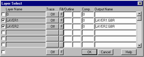 From the Main Menu, press the Merge Layers button which will open the Film Merge Menu. First give the film a name, (for this example we used film1.pho). Click Add so that it appears in the section below. Select both Gerber Files (LAYER1.GBR and LAYER2.GBR). Double Click on each one to add it to the Layer Name section, (as seen below). On LAYER2.GBR, change the Paint/Scratch option to Scratch. Also, make sure the Output type is set to RS274X and check the View Films options. Press OK when you're done. 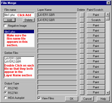
|
|
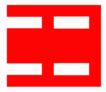
Click on the Start Translation button from the Main Menu. When complete, the file can be opened in GBRVU by pressing the View Gerber Data button. Notice that our drawing now has the same effect as the hatch created in AutoCAD and has been merged into one layer. |
|
For more information on this topic, take a look at the following Flash Demonstration, |
|