Translating AutoCAD Files using the De-Embedding Feature

This page describes the basic procedure for translating DXF file to Gerber using our new De-Embedding feature. Polygon De-Embedding is the ability to take a layer full of polygons that contain other polygons, figure out which surrounds which, and produce a Gerber output that sorts out the changes in polarity due to each boundary.

You can read more about the De-Embedding feature at...
New Polygon De-Embedding for ASM 500


de-emb1.gif


Autocad File

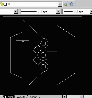
Let's look at the following example. The design in Autocad has polygons inside of polygons, all on layer 0. Running it through ASM500 will not give the proper result. The outside polygons will simply cover the inside polygons, instead of having the inside polygons clear.

Let's see how the De-Embedding feature helps.


de-emb2.gif


STEP 1

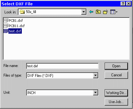
Start ASM500 and select the file to convert. Make sure the units are correct.


de-emb3.gif

STEP 2

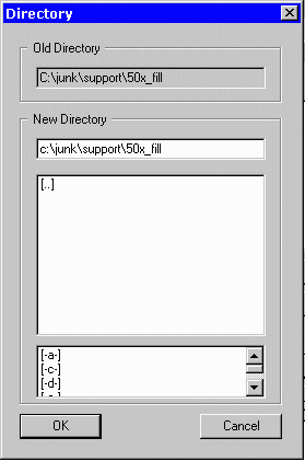
From the Select DXF File menu, click on Working Dir... button to open the Directory menu. Make sure the working directory is the same as the one where the .dxf file is located by Clicking OK.

Now open the AutoCAD file to be translated. For this example we'll use a file called test.dxf


STEP 3

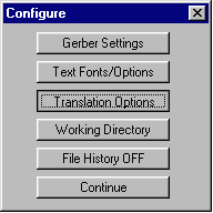
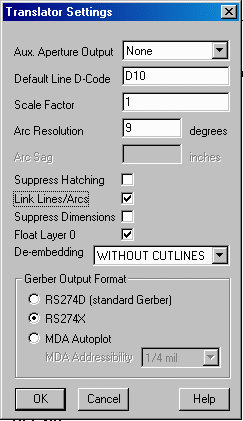
From the ASM 500 Main Menu, Click on the Configure Trans button. From the Configure Menu (shown below), Click on Translation Options. The Translator Settings Dialog will appear (shown at right).

Make sure the Gerber Output Format is set to RS274X, and set the De-Embedding to with cutlines. Click OK and then Continue from
the Configure Menu.

config_trans_options.gif


de-emb4.gif


STEP 4

From the Main Menu, Click on Set Apertures. If an aperture file has already been created for the .dxf, select it and press open. If not, create an aperture file with the same (or similar) name as the .dxf and press Open. For this example, our aperture file is called test.apt.

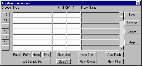
Once you open the aperture file, the Aperture Menu will appear. If you just created the .apt file, there will not be any apertures set. If you've opened an existing one, it will probably have defined apertures in place. If so, clear them so the menu is blank.

mixer_apt1.gif

Click on the Add Default Set button. A list of default apertures will appear. Click on the Flash Circles button. The Flash Circles/Donuts Menu will appear with a list of circles and donuts in the .dxf file, (shown below). Click OK to add them to the Apertures Menu.


mixer_types_and_blocks.gif


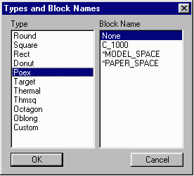
From the Aperture Menu, Click on a blank D-Code Number. The Types and Blocks Menu will appear, (shown at left). Select Poex from the list of types and Click OK.

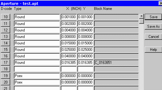
Repeat this process with another blank D-Code Number. (We've chosen D-Codes 19 and 20 for this example).

Your Aperture Menu should now look like the one below. Press Save to Continue.

de-emb6.gif


STEP 5

From the Main Menu, Click on the Select Layers button. The Layer Table will appear. Make sure that the layers you wish to translate have been selected with a checkmark next to their layer name. Set each layer(s) to O - for Outline under the Fill/Outline Option. Notice that the two POEX apertures, (19 and 20) have appeared in the table.

de-emb7.gif

Click OK to close the Layer Table.


start_trans.gif


STEP 6

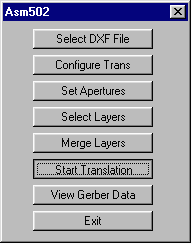
Start the Translation from the Main Menu by Clicking on the Start Translation button.

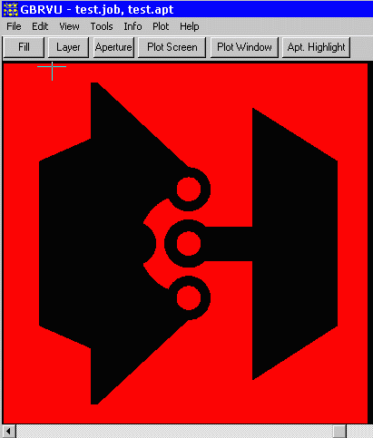
Finally, Click on the View Gerber Data button from the Main Menu to see the Translation results.

Notice the polarity change in the Gerber output. The inside polygons are cleared from the filled area which is what we want.


de-emb8.gif