
|
Sample App - Producing DXF Polylines and CirclesBelow we provide some commented code that illustrates how to use the circularize function to take a collection of vertices (let's assume they represent polygons generated by some 2D Boolean operator) and produce AutoCAD DXF using polylines. The AutoCAD polyline can contain segments and arcs. Also, though it is legal to create a single 360 degree polyline with one arc, if we run into that condition we want to write it to DXF as a circle.
    // DXF output Example of Circularize Library Usage
    // Get a Handle (normally would check to see if handle is valid)

    CircularizeIndex = CircularizeDllInit_MT();

    // Arcsag [Chord Error] required; check it is set to a reasonable value
    // insures the value is not too fine for the data grid

    if(ArcSag/UserUnit < 10.0)
      SetArcsag(10.0, CircularizeIndex);
    else
      SetArcsag(ArcSag/UserUnit, CircularizeIndex);

    // Inputs
    // xy is the input array of xy points defining the polygon
    // Nvrt is the number of vertices making up the polygon
    // first vertex and last vertex must be same point (like in GDSII)

    rtn = Circularize(Nvrt, xy, &pCircularData, &pNum, CircularizeIndex);


    // a return code of 1 means function operated successfully
    if(rtn == 1) {

    // if only one item returned, implies we have a circle (a single arc)
      if(pNum == 1) {

        xval   = pCircularData[0];        // starting point X
        yval   = pCircularData[1];        // starting point Y
        xc     = pCircularData[2];        // center X
        yc     = pCircularData[3];        // center Y
        radius = fabs(pCircularData[4]);  // absolute value of radius

        r0 = radius * UserUnit;
        x0 = xc * UserUnit;
        y0 = yc * UserUnit;

    // the following lines write out a CIRCLE in DXF
        fprintf(FCIF," 0\n CIRCLE\n 8\n %s\n", CurrentLayerName);
        fprintf(FCIF," 10\n%lf\n 20\n%lf\n 40\n%lf\n",x0,y0,r0);


    // if we end up here, there are multiple elements in the composite curve
    // we will loop through each element, check if it is an arc or segment
    // and print the appropriate data for the polyline

      } else {
        //first we print the preamble for the polyine
        fprintf(FCIF,"0\n POLYLINE\n 8\n%s\n 66\n 1\n 70\n 1\n 40\n 0.0\n 41\n0.0\n",CurrentLayerName);
        // now loop through the elements
        for (I = 0; I < pNum; I++) {
          xval   = pCircularData[I*5];
          yval   = pCircularData[I*5+1];
          radius = pCircularData[I*5+4];
          if(radius != 0.0) {	// if not zero then we have an arc
            xc = pCircularData[I*5+2];
            yc = pCircularData[I*5+3];
            a1 = atan2(pCircularData[I*5+1]    -yc,pCircularData[I*5]    -xc);
            a2 = atan2(pCircularData[(I+1)*5+1]-yc,pCircularData[(I+1)*5]-xc);
            if(radius > 0.) {
              if(a2 < a1)
                a2 += TWOPI;
            } else {
              if(a2 > a1)
                a2 -= TWOPI;
            }
            da = a2 - a1;
            bulge = tan(da/4.0);   // special to DXF
            a1 *= (360.0 / TWOPI);
            a2 *= (360.0 / TWOPI);
            x0 = xval * UserUnit;
            y0 = yval * UserUnit;
            fprintf(FCIF,"  0\nVERTEX\n  8\n%s\n 10\n%lf\n 20\n%lf\n 42\n%lf\n",CurrentLayerName,x0,y0,bulge);
            // if we branch here we have a straight segment
          } else {
            x0 = xval * UserUnit;
            y0 = yval * UserUnit;
            fprintf(FCIF,"  0\nVERTEX\n  8\n%s\n 10\n%lf\n 20\n%lf\n", CurrentLayerName,x0,y0);
          }
        } /* for */
        fprintf(FCIF,"  0\nSEQEND\n  8\n%s\n",
          CurrentLayerName);

      }
      // done so release the memory used for the output
      ReleaseDblArray(pCircularData);


    } else {
      // if we end up here - the function could not circularize the polygon
      // output using the same xy vertices as passed into the function
      dp = DbleData;
      // DXF specific code for a polyline built from segments
      fprintf(FCIF,"  0\nPOLYLINE\n  8\n%s\n 66\n     1\n 70\n     1\n 40\n0.0\n 41\n0.0\n", CurrentLayerName);
      for (I = 0; I < Nvrt*2-2; I += 2) {
        x0 = *(dp++) * UserUnit;
        y0 = *(dp++) * UserUnit;
        fprintf(FCIF,"  0\nVERTEX\n  8\n%s\n 10\n%lf\n 20\n%lf\n",CurrentLayerName,x0,y0);
      } /* for */
      fprintf(FCIF,"  0\nSEQEND\n  8\n%s\n",CurrentLayerName);
    }


    // release the thread handle and clean up
    if(CircularizeIndex != -1) {
      CircularizeDllClose_MT(CircularizeIndex);
    }
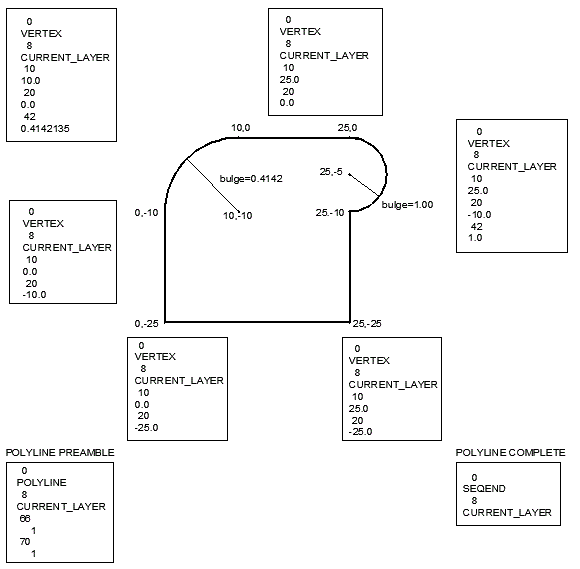
Annotated PolylineA polyline with two arcs was drawn using AutoCAD and saved as a DXF file. After removing "uneccessary" entries such as handles and Z coordinates the diagram below shows the syntax. 
|